Tuesday, March 15, 2016

Opto Couplers – Types Based on Applications


Opto Couplers – Types & Applications


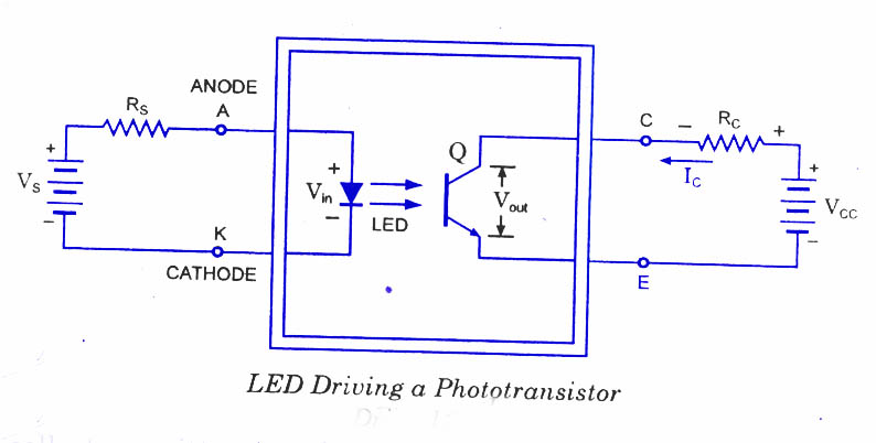
A lot of electronic equipment nowadays is using opt coupler in the circuit. An opt coupler or sometimes refer to as opt isolator allows two circuits to exchange signals yet remain electrically isolated. This is usually accomplished by using light   to relay the signal. The standard opt coupler circuits design uses a LED shining on a phototransistor-usually it is a npn transistor and not pnp. The signal is applied to the LED, which then shines on the transistor in the IC.
The light is proportional to the signal, so the signal is thus transferred to the photo-transistor. Opt couplers may also comes in few module such as the SCR, photodiodes, TRIAC of other semiconductor switch as an output, and incandescent lamps, neon bulbs or other light source.
Most commonly used is an opto-coupler MOC3021 an LED diac type combination. This IC is interfaced with a microcontroller and an LED is connected in series to the IC, which glows to indicate a logic High pulse from the microcontroller so that we can know that current is flowing in internal LED of the opto-IC. When logic high is given current flows through LED from pin1 to 2. So in this process LED light falls on DIAC causing 6 & 4 to close. During each half cycle current flows through gate, series resistor and through opto-diac for the main thyristor / triac to trigger for the load to operate.
The opto coupler usually found in switch mode power supply circuit in many electronic equipment. It is connected in between the primary and secondary section of power supplies. The opto-coupler application or function in the circuit is to:
  1. Monitor high voltage
  2. Output voltage sampling for regulation
  3. System control micro for power ON/OFF
  4. Ground isolation
This is the principle used in Opto−Diacs, the Opto-Diacs are available in form of ICs and can be implemented using a simple circuitry.
Simply provide a small pulse at the right time to the Light Emitting Diode in the package. The light produced by the LED activates the light sensitive properties of the diac and the power is switched on. The isolation between the low power and high power circuits in these optically connected devices is typically several thousand volts.

Opto-Diacs Pin Description:
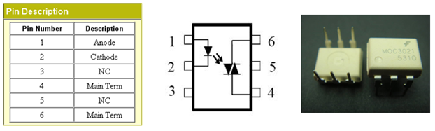
Opto-Diacs

4 Different Opto Couplers available

1. MOC3020

It comes in 6-pin DIP is shown in figure:
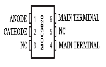
MOC3020

Working Principle of MOC3020:

The MOC3020 are designed for interfacing between electronic controls and power triac to control resistive and inductive loads for Vac operations. The principle used in opto-coupler is, MOC’s are promptly available in integrated circuit form and don’t require very complex circuitry to make them work. Simply give a small pulse at the right time to the LED in the package. The light produced by the LED activates the light sensitive properties of the diac and the power is switched on. The isolation between the low power and high power circuits in these optically connected devices is typically few thousand volts.

Features of MOC3020:

  • 400 V Photo-TRIAC Driver Output
  • Gallium-Arsenide-Diode infrared source and optically-coupled silicon triac driver
  • High isolation – 500 Vpeak
  • Output driver designed for 220 Vac
  • Standard 6-terminal plastic DIP
  • Directly interchangeable with Motorola MOC3020, MOC3021 and MOC3022

 Typical applications of MOC3020:

  • Solenoid/valve controls
  • Lamp ballasts
  • Interfacing microprocessors to 115/240 Vac peripherals
  • Motor controls
  • Incandescent lamp dimmers

 Application of MOC3020:

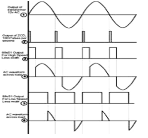
The circuit shown below is a typical circuit used for AC load control from microcontroller, one LED can be connected in series with MOC3021, LED to indicate when high is given from micro controller such that we can know that current is flowing in internal LED of the opto-coupler.The idea is to use a power lamp whose activation requires mains AC as opposed to a DC voltage. That’s way, the mains AC power that we’re trying to switch the lamp and no external power supply is required. To switch the AC current to the lamp, we have to use an opto-coupled triac, lamp and a diac is shown in circuit below. A triac is said to be as an AC controlled switch. It has three terminals M1, M2 and gate. A TRIAC, lamp load and a supply voltage are connected in series. When supply is ON at positive cycle then the current flows through lamp, resistors, diac, and gate and reaches the supply and then only lamp glows for that half cycle directly through the M2 and M1 terminal of the triac. In negative half cycle the same thing repeats. Thus the lamp glows in both the cycles in a controlled manner depending upon the triggering pulses at the opto isolator as seen on the graph below. If this is given to a motor instead of lamp the power is controlled resulting in speed control.
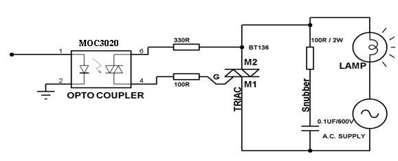
MOC3020 cir
MOC3020 circuit

 2. MOC3021

MOC3021 is an opto-coupler designed for triggering TRIACS. By using this we can trigger anywhere in the cycle, so can call them as non-zero opto-coupler. MOC3021 are very widely used and can be quite easily obtained from many sources. It comes in 6-pin DIP shown in figure.

Pin Description:

Pin 1: Anode
Pin 2: Cathode
Pin 3: No connection (NC)
Pin 4: Main terminal
Pin 5: No connection (NC)
Pin 6: Main terminal

Features:

  • 400 V Photo-triac driver output
  • Gallium-Arsenide-Diode Infrared Source and Optically-Coupled Silicon triac driver
  • High Isolation 7500 V Peak
  • Output Driver Designed for 220 Vac
  • Standard 6-terminal plastic DIP
There are many applications of MOC3021 such as solenoid/valve controls, lamp ballasts, interfacing microprocessors to 115/240 Vac peripherals, motor controls and incandescent lamp dimmers.

Application of MOC3021:

From the below circuit, the most commonly used is an opto-coupler MOC3021 with an LED diac type combination. Additionally while using this with microcontroller and one LED can be connected in series with MOC3021, LED to indicate when high is given from micro controller such that we can know that current is flowing in internal LED of the opto-coupler. When logic high is given then the current flows through the LED from pin 1 to 2. So in this process LED light falls on DIAC causing 6 and 4 to close. During each half cycle current flows through gate, series resistor and through opto-diac for the main thyristor / triac to trigger for the load to operate.

3. MCT2E

The MCT2E series of opto-coupler devices each consist of gallium arsenide infrared LED and a silicon NPN phototransistor. They are packaged in a 6-pin DIP package and available in wide-lead spacing.
Pin 1: Anode.
Pin 2: Cathode.
Pin 3: No connection.
Pin 4: Emitter.
Pin 5: Collector.
Pin 6: Base.

Features:

  • Isolation test voltage 5000 VRMS
  • Interfaces with common logic families
  • Input-output coupling capacitance < 0.5 pF
  • Industry standard dual-in-line 6 pin package
  • Compliant to RoHS directive 2002/95/EC
The opto-coupler usually found in switch mode power supply circuit, read relay driving, industrial controls, digital logic inputs and in many electronic equipments

Application of MCT2E:

It is a combination of 1 LED and a transistor. Pin 6 of transistor is not generally used and when light falls on the base-emitter junction then it switches and pin5 goes to zero.
  • When logic zero is given as input then the light doesn’t fall on transistor so it doesn’t conduct which gives logic one as output.
  • When logic 1 is given as input then light falls on transistor so that it conducts, that makes transistor switched ON and it forms short circuit this makes the output is logic zero as collector of transistor is connected to ground.

4. MOC363

The MOC3063 devices consist of gallium arsenide infrared emitting diodes optically coupled to monolithic silicon detectors performing the functions of zero voltage crossing bilateral triac drivers. It is also a 6-pin DIP shown in figure:
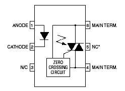
MOC3063

Pin Description:

Pin 1: Anode
Pin 2: Cathode
Pin 3: No connection (NC)
Pin 4: Main terminal
Pin 5: No connection (NC)
Pin 6: Main terminal

Features:

  • Simplifies logic control of 115/240 Vac power
  • Zero crossing voltage
  • dv/dt of 1500 V/µs typical, 600 V/µs guaranteed
  • VDE recognized
  • Underwriters Laboratories (UL) recognized

Applications:

  • Solenoid/valve controls
  • Static power switches
  • Temperature controls
  • AC motor starters and drivers
  • Lighting controls
  • E.M. contactors
  • Solid state relay

 Working of MOC3063:

From the circuit, we have an opto-coupler MOC3063 with an LED SCR type combination. Additionally while using this opto-coupler with microcontroller and one LED can be connected in series with MOC3063 LED to indicate when high is given from micro controller such that we can know that current is flowing in internal LED of the opto-coupler. When logic high is given then the current flows through LED from pin 1 to 2. The LED light falls on SCR causing 6 and 4 to close only at the zero cross of the supply voltage. During each half cycle current flows through SCR gate, external series resistor and through SCR for the main thyristor/triac to trigger for the load at the beginning of the supply cycle always to operate.
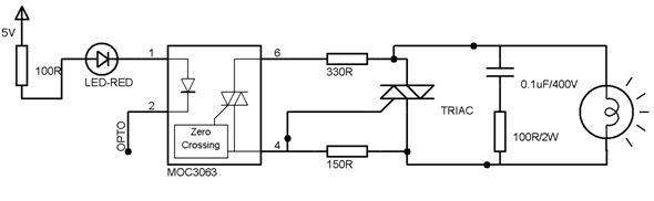
MOC3063-circuit

Optocoupler Characteristics, Types and Application

Optocoupler Characteristics, Types and Application

We know from our tutorials about Transformers that they not only provide higher or lower voltage differences between their primary and secondary windings, but they also provide “electrical isolation” between the higher voltages on the primary side and the lower voltage on the secondary side.
In other words, transformers isolate the primary input voltage from the secondary output voltage using electromagnetic coupling by means of a magnetic flux circulating within the iron laminated core. But we can also provide electrical isolation between an input source and an output load using just light by using a very common and valuable electronic component called an Optocoupler.
typical 4n35 optocoupler
An Optocoupler, also known as an Opto-isolator or Photo-coupler, is an electronic components that interconnects two separate electrical circuits by means of a light sensitive optical interface.
The basic design of an Optocoupler consists of an LED that produces infra-red light and a semiconductor photo-sensitive device that is used to detect the emitted infra-red beam. Both the LED and photo-sensitive device are enclosed in a light-tight body or package with metal legs for the electrical connections as shown.
An optocoupler or opto-isolator consists of a light emitter, the LED and a light sensitive receiver which can be a single photo-diode, photo-transistor, photo-resistor, photo-SCR, or a photo-TRIAC and the basic operation of an optocoupler is very simple to understand.

Phototransistor Optocoupler

phototransistor optocoupler
Assume a photo-transistor device as shown. Current from the source signal passes through the input LED which emits an infra-red light whose intensity is proportional to the electrical signal.
This emitted light falls upon the base of the photo-transistor, causing it to switch-ON and conduct in a similar way to a normal bipolar transistor.
The base connection of the photo-transistor can be left open for maximum sensitivity or connected to ground via a suitable external resistor to control the switching sensitivity making it more stable.
When the current flowing through the LED is interrupted, the infra-red emitted light is cut-off, causing the photo-transistor to cease conducting. The photo-transistor can be used to switch current in the output circuit. The spectral response of the LED and the photo-sensitive device are closely matched being separated by a transparent medium such as glass, plastic or air. Since there is no direct electrical connection between the input and output of an optocoupler, electrical isolation up to 10kV is achieved.
Optocouplers are available in four general types, each one having an infra-red LED source but with different photo-sensitive devices. The four optocouplers are called the: Photo-transistor, Photo-darlington, Photo-SCR and Photo-triac as shown below.

Optocoupler Types

optocoupler types
The photo-transistor and photo-darlington devices are mainly for use in DC circuits while the photo-SCR and photo-triac allow AC powered circuits to be controlled. There are many other kinds of source-sensor combinations, such as LED-photodiode, LED-LASER, lamp-photoresistor pairs, reflective and slotted optocouplers.
Simple homemade optocouplers can be constructed by using individual components. An Led and a photo-transistor are inserted into a rigid plastic tube or encased in heat-shrinkable tubing as shown. The advantage of this home-made optocoupler is that tubing can be cut to any length you want and even bent around corners. Obviously, tubing with a reflective inner would be more efficient than dark black tubing.

Home-made Optocoupler

home made optocoupler

Optocoupler Applications

Optocouplers and opto-isolators can be used on their own, or to switch a range of other larger electronic devices such as transistors and triacs providing the required electrical isolation between a lower voltage control signal and the higher voltage or current output signal. Common applications for optocouplers include microprocessor input/output switching, DC and AC power control, PC communications, signal isolation and power supply regulation which suffer from current ground loops, etc. The electrical signal being transmitted can be either analogue (linear) or digital (pulses).
In this application, the optocoupler is used to detect the operation of the switch or another type of digital input signal. This is useful if the switch or signal being detected is within an electrically noisy environment. The output can be used to operate an external circuit, light or as an input to a PC or microprocessor.

An Optotransistor DC Switch

optotransistor switch
As well as detecting DC signals and data, Opto-triac isolators are also available which allow AC powered equipment and mains lamps to be controlled. Opto-coupled triacs such as the MOC 3020, have voltage ratings of about 400 volts making them ideal for direct mains connection and a maximum current of about 100mA. For higher powered loads, the opto-triac may be used to provide the gate pulse to another larger triac via a current limiting resistor as shown.

Triac Optocoupler Application

triac optocoupler application
This type of optocoupler configuration forms the basis of a very simple solid state relay application which can be used to control any AC mains powered load such as lamps and motors. Also unlike a thyristor (SCR), a triac is capable of conducting in both halves of the mains AC cycle with zero-crossing detection allowing the load to receive full power without the heavy inrush currents when switching inductive loads.
Optocouplers and Opto-isolators are great electronic devices that allow devices such as power transistors and triacs to be controlled from a PC’s output port, digital switch or from a low voltage data signal such as that from a logic gate. The main advantage of opto-couplers is their high electrical isolation between the input and output terminals allowing relatively small digital signals to control much large AC voltages, currents and power.
An optocoupler can be used with both DC and AC signals with optocouplers utilizing a SCR (thyristor) or triac as the photo-detecting device are primarily designed for AC power-control applications. The main advantage of photo-SCRs and photo-triacs is the complete isolation from any noise or voltage spikes present on the AC power supply line as well as zero-crossing detection of the sinusoidal waveform which reduces switching and inrush currents protecting any power semiconductors used from thermal stress and shock.
Characteristics of an Optocoupler: 
  
optocoupler-characteristics

  
Current Transfer Ratio (CTR). One of the most important parameters of an optocoupler device is its optocoupling efficiency. This parameter is maximized by closely matching spectrally the LED and the phototransistor (which usually operate in the infra-red range). The optocoupling efficiency of an optocoupler may be conveniently specified by the output-to-input current transfer ratio (CTR) i.e., the ratio of the output current Ic (measured at the collector terminal of the phototransistor), to the input current IF flowing into the LED. 
Input-to-Output Isolation Voltage (Viso). This is the maximum potential difference (dc) that can be allowed to exist between the input and output terminals. Typical values range from 500 V to 4 kV. 
Maximum Collector-Emitter Voltage, VCE (max). This is the maximum allowable dc voltage that can be applied across the output transistor. Typical values may vary from 20 to 80 volts.  
Bandwidth. This is the typical maximum signal frequency (in kHz) that can be use­fully passed through the optocoupler when the device is operated in its normal mode. Typical values vary from 20 to 500 kHz, depending on the type of device construction. 
Response Time. Divided into rise time tr and fall time t*. For a phototransistor output stages, tr andtr are usually around 2 to 5 us. 
A simple isolating optocoupler uses a single phototransistor output stage and is usually housed in a six-pin package, with the base terminal of the phototransistor externally available. In nor­mal use the base is left open circuit, and under such a condition the optocoupler has a minimum CTR value of 20 % and a useful bandwidth of 300 kHz. 

Monday, March 14, 2016

Use of MPPT in CONSTANT VOLTAGE output boast converter in MATLAB


What is MAXIMUM POWER Point ??

This section covers the theory and operation of "Maximum Power Point Tracking" as used in solar electric charge controllers.
A MPPT, or maximum power point tracker is an electronic DC to DC converter that optimizes the match between the solar array (PV panels), and the battery bank or utility grid. To put it simply, they convert a higher voltage DC output from solar panels (and a few wind generators) down to the lower voltage needed to charge batteries.
(These are sometimes called "power point trackers" for short - not to be confused with PANEL trackers, which are a solar panel mount that follows, or tracks, the sun).

So what do you mean by "optimize"?

Solar cells are neat things. Unfortunately, they are not very smart. Neither are batteries - in fact batteries are downright stupid. Most PV panels are built to put out a nominal 12 volts. The catch is "nominal". In actual fact, almost all "12 volt" solar panels are designed to put out from 16 to 18 volts. The problem is that a nominal 12 volt battery is pretty close to an actual 12 volts - 10.5 to 12.7 volts, depending on state of charge. Under charge, most batteries want from around 13.2 to 14.4 volts to fully charge - quite a bit different than what most panels are designed to put out.
OK, so now we have this neat 130 watt solar panel. Catch #1 is that it is rated at 130 watts at a particular voltage and current. The Kyocera KC-130 is rated at 7.39 amps at 17.6 volts. (7.39 amps times 17.6 volts = 130 watts).

Now the Catch 22

Why 130 Watts does NOT equal 130 watts

Where did my Watts go?

So what happens when you hook up this 130 watt panel to your battery through a regular charge controller?

Unfortunately, what happens is not 130 watts.

Your panel puts out 7.4 amps. Your battery is setting at 12 volts under charge: 7.4 amps times 12 volts = 88.8 watts. You lost over 41 watts - but you paid for 130. That 41 watts is not going anywhere, it just is not being produced because there is a poor match between the panel and the battery. With a very low battery, say 10.5 volts, it's even worse - you could be losing as much as 35% (11 volts x 7.4 amps = 81.4 watts. You lost about 48 watts.
One solution you might think of - why not just make panels so that they put out 14 volts or so to match the battery?
Catch #22a is that the panel is rated at 130 watts at full sunlight at a particular temperature (STC - or standard test conditions). If temperature of the solar panel is high, you don't get 17.4 volts. At the temperatures seen in many hot climate areas, you might get under 16 volts. If you started with a 15 volt panel (like some of the so-called "self regulating" panels), you are in trouble, as you won't have enough voltage to put a charge into the battery. Solar panels have to have enough leeway built in to perform under the worst of conditions. The panel will just sit there looking dumb, and your batteries will get even stupider than usual.
Nobody likes a stupid battery.

WHAT IS MAXIMUM POWER POINT TRACKING?

There is some confusion about the term "tracking":
Panel tracking - this is where the panels are on a mount that follows the sun. The most common are the Zomeworks and Wattsun. These optimize output by following the sun across the sky for maximum sunlight. These typically give you about a 15% increase in winter and up to a 35% increase in summer. 
This is just the opposite of the seasonal variation for MPPT controllers. Since panel temperatures are much lower in winter, they put out more power. And winter is usually when you need the most power from your solar panels due to shorter days.
Maximum Power Point Tracking is electronic tracking - usually digital. The charge controller looks at the output of the panels, and compares it to the battery voltage. It then figures out what is the best power that the panel can put out to charge the battery. It takes this and converts it to best voltage to get maximum AMPS into the battery. (Remember, it is Amps into the battery that counts). Most modern MPPT's are around 93-97% efficient in the conversion. You typically get a 20 to 45% power gain in winter and 10-15% in summer. Actual gain can vary widely depending weather, temperature, battery state of charge, and other factors.
Grid tie systems are becoming more popular as the price of solar drops and electric rates go up. There are several brands of grid-tie only (that is, no battery) inverters available. All of these have built in MPPT. Efficiency is around 94% to 97% for the MPPT conversion on those.

How Maximum Power Point Tracking works

Here is where the optimization, or maximum power point tracking comes in. Assume your battery is low, at 12 volts. A MPPT takes that 17.6 volts at 7.4 amps and converts it down, so that what the battery gets is now 10.8 amps at 12 volts. Now you still have almost 130 watts, and everyone is happy.
Ideally, for 100% power conversion you would get around 11.3 amps at 11.5 volts, but you have to feed the battery a higher voltage to force the amps in. And this is a simplified explanation - in actual fact the output of the MPPT charge controller might vary continually to adjust for getting the maximum amps into the battery.
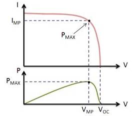
On the left is a screen shot from the Maui Solar Software "PV-Design Pro" computer program (click on picture for full size image). If you look at the green line, you will see that it has a sharp peak at the upper right - that represents the maximum power point. What an MPPT controller does is "look" for that exact point, then does the voltage/current conversion to change it to exactly what the battery needs. In real life, that peak moves around continuously with changes in light conditions and weather.
A MPPT tracks the maximum power point, which is going to be different from the STC (Standard Test Conditions) rating under almost all situations. Under very cold conditions a 120 watt panel is actually capable of putting over 130+ watts because the power output goes up as panel temperature goes down - but if you don't have some way of tracking that power point, you are going to lose it. On the other hand under very hot conditions, the power drops - you lose power as the temperature goes up. That is why you get less gain in summer.
MPPT's are most effective under these conditions:
Winter, and/or cloudy or hazy days - when the extra power is needed the most.
  • Cold weather - solar panels work better at cold temperatures, but without a MPPT you are losing most of that. Cold weather is most likely in winter - the time when sun hours are low and you need the power to recharge batteries the most.
  • Low battery charge - the lower the state of charge in your battery, the more current a MPPT puts into them - another time when the extra power is needed the most. You can have both of these conditions at the same time.
  • Long wire runs - If you are charging a 12 volt battery, and your panels are 100 feet away, the voltage drop and power loss can be considerable unless you use very large wire. That can be very expensive. But if you have four 12 volt panels wired in series for 48 volts, the power loss is much less, and the controller will convert that high voltage to 12 volts at the battery. That also means that if you have a high voltage panel setup feeding the controller, you can use much smaller wire.
Ok, so now back to the original question - What is a MPPT?

How a Maximum Power Point Tracker Works:

The Power point tracker is a high frequency DC to DC converter. They take the DC input from the solar panels, change it to high frequency AC, and convert it back down to a different DC voltage and current to exactly match the panels to the batteries. MPPT's operate at very high audio frequencies, usually in the 20-80 kHz range. The advantage of high frequency circuits is that they can be designed with very high efficiency transformers and small components. The design of high frequency circuits can be very tricky because the problems with portions of the circuit "broadcasting" just like a radio transmitter and causing radio and TV interference. Noise isolation and suppression becomes very important.
There are a few non-digital (that is, linear) MPPT's charge controls around. These are much easier and cheaper to build and design than the digital ones. They do improve efficiency somewhat, but overall the efficiency can vary a lot - and we have seen a few lose their "tracking point" and actually get worse. That can happen occasionally if a cloud passed over the panel - the linear circuit searches for the next best point, but then gets too far out on the deep end to find it again when the sun comes out. Thankfully, not many of these around any more.
The power point tracker (and all DC to DC converters) operates by taking the DC input current, changing it to AC, running through a transformer (usually a toroid, a doughnut looking transformer), and then rectifying it back to DC, followed by the output regulator. In most DC to DC converters, this is strictly an electronic process - no real smarts are involved except for some regulation of the output voltage. Charge controllers for solar panels need a lot more smarts as light and temperature conditions vary continuously all day long, and battery voltage changes.

Smart power trackers

All recent models of digital MPPT controllers available are microprocessor controlled. They know when to adjust the output that it is being sent to the battery, and they actually shut down for a few microseconds and "look" at the solar panel and battery and make any needed adjustments. Although not really new (the Australian company AERL had some as early as 1985), it has been only recently that electronic microprocessors have become cheap enough to be cost effective in smaller systems (less than 1 KW of panel). MPPT charge controls are now manufactured by several companies, such as Outback Power, Xantrex XW-SCC, Blue Sky Energy, Apollo Solar, Midnite Solar, Morningstar and a few others.

Wednesday, February 3, 2016

Low voltage ride through

Low voltage ride through

In electric power systems, low-voltage ride through (LVRT), or fault ride through (FRT), sometimes under-voltage ride through (UVRT), is the capability of electric generators to stay connected in short periods of lower electric network voltage (cf. voltage dip). It is needed at distribution level (wind parks, PV systems, distributed cogeneration, etc.) to avoid that a short circuit on HV or EHV level will lead to a wide-spread loss of generation. Similar requirements for critical loads such as computer systems and industrial processes are often handled through the use of an uninterruptible power supply (UPS) or capacitor bank to supply make-up power during these events.

General concept
Many generator designs use electric current flowing through windings to produce the magnetic field on which the motor or generator operates. This is in contrast to designs that use permanent magnets to generate this field instead. Such devices may have a minimum working voltage, below which the device does not work correctly, or does so at greatly reduced efficiency. Some will cut themselves out of the circuit when these conditions apply. This effect is more severe in doubly-fed induction generators (DFIG), which have two sets of powered magnetic windings, than in squirrel-cage induction generators which have only one. Synchronous generators may slip and become unstable, if the voltage of the stator winding goes down below a certain threshold.
Risk of chain reaction
In a grid containing many distributed generators subject to a low-voltage disconnection, it is possible to cause a chain reaction that takes other generators offline as well. This can occur in the event of a voltage dip that causes one of the generators to disconnect from the grid. As voltage dips are often caused by too little generation for the load in a distribution grid, removing generation can cause the voltage to drop further. This may bring the voltage down enough to cause another generator to trip, lower the voltage even further, and may cause a cascading failure.
Ride through systems
Modern large-scale wind turbines, typically 1 MW and larger, are normally required to include systems that allow them to operate through such an event, and thereby “ride through” the low voltage. Similar requirements are now becoming common on large solar power installations that likewise might cause instability in the event of a disconnect. Depending on the application the device may, during and after the dip, be required to:
disconnect temporarily from the grid, but reconnect and continue operation after the dip
stay operational and not disconnect from the grid
stay connected and support the grid with reactive power (defined as the reactive current of the positive sequence of the fundamental)
Standards
A variety of standards exist and generally vary across jurisdictions. Examples of the such grid codes are the German BDEW grid code and its supplements 2, 3, and 4 as well as the National Grid Code in UK.
Testing
Testing of the devices with less than 16 Amp rated current is described in the standard IEC 61000-4-11 and for higher current devices in IEC 61000-4-34. For wind turbines the LVRT testing is described in the standard IEC 61400-21 (2nd edition August 2008). More detailed testing procedures are stated in the German guideline FGW TR3 (Rev.22).

Anti Islanding Protection

What is Anti-Islanding?

Power lines and solar panels


Electric utility companies refer to residential grid-tie solar power arrays as distributed generation (DG) generators. They use this term because your solar panels are producing and distributing electrical power back into our utility grid. 
Islanding refers to the condition of a DG generator that continues to feed the circuit with power, even after power from the electric utility grid has been cut off. Islanding can pose a dangerous threat to utility workers, who may not realize that a circuit is still "live" while attempting to work on the line.
Distributed generators must detect islanding and immediately stop feeding the utility lines with power. This is known as anti-islanding. A grid-tied solar power system is required by law to have a gridtie inverter with an anti-islanding function, which senses when a power outage occurs and shuts itself off. 


One common misconception is that a grid tied system will continue to generate power during a blackout. Unless there is abattery back-up system, the gridtie solar system will not produce power when the grid is down.
The common example of islanding is a grid supply line that has solar panels attached to it. In the case of a blackout, the solar panels will continue to deliver power as long as irradiance is sufficient. In this case, the supply line becomes an "island" with power surrounded by a "sea" of unpowered lines. For this reason, solar inverters that are designed to supply power to the grid are generally required to have some sort of automatic anti-islanding circuitry in them.

In intentional islanding, the generator disconnects from the grid, and forces the distributed generator to power the local circuit. This is often used as a power backup system for buildings that normally sell their excess power to the grid.

What is the difference between Socket and Port?

Socket Sockets allow communication between two different processes on the same or different machines. To be more precise, it's a way to ...