Saturday, March 26, 2016

Solar night light - simple circuit


Simple Solar Circuits:
How to get started adding solar power to your small electronics projects. Use the sun to power small solar and battery powered night lights, garden lights, and decorations for halloween.

SolarCircuits - 12   SolarCircuits - 11

The first part of a solar circuit is  a device for collecting sunlight. To keep things simple, we’re using a single nicely made small solar panel for all of these circuits. The panel that we’re using for these circuits is this one, part number PWR1241 from BG Micro, about $3 each. This is a monolithic copper indium diselenide solar panel, apparently printed on a 60mm square of glass and epoxy coated for toughness. On the back of the panel are two (thin) solderable terminals, with marked polarity. (While you can solder directly to the terminals, be sure to stress-relieve the connections, e.g., with a blob of epoxy over your wires.) In full sunlight the panel is specified to produce 4.5 V at up to 90 mA, although 50 mA seems like a more typical figure.
[Before we move onto our first examples, a word of caution: These are small simple circuits. In building these, we will quite intentionally gloss over a number of minor details and issues that are unimportant at these low powers, but could become critical if you were to try to scale up.]
Direct Drive:
The most obvious way to use power from a solar panel is to connect your load directly to the output leads of the solar panel.
solar1
Here are a couple of examples of this in practice:

SolarCircuits - 02   SolarCircuits - 01
On the left, we’ve hooked up one of our little solar panels directly to a small motor taken from an old CD player. When you set it out in the sunlight or bring it close to a lamp, the motor starts to spin. On the right we’ve hooked one of the panels right up to a high-power blue LED. The reason that we’ve used a high-power LED here is that it can easily withstand 50-90 mA from the solar panel– a “regular” LED designed for 20 mA would be destroyed by that current. (The LED is the same type that we used for our high-power LED blinking circuit.)
Interruption-resistant direct drive:
The “direct drive” circuits work well for their design function, but are rather basic. They provide no energy storage, and so are quite vulnerable to blinking out when a bird or cloud passes overhead. For some applications, like running a small fan or pump, that may be perfectly acceptable. For other cases, like powering a microcontroller or other computer, a brief power interruption can be disruptive. Our next circuit design adds a supercapacitor as a “flywheel” to provide continued power during brief interruptions.
solar2
SolarCircuits - 03
Instead of adding a single supercapacitor, you might notice that we’ve actually added two. That’s because the supercaps that we had on hand are rated for 2.75 V– not enough to handle the 4.5 V output of the panel when sunlight is present. To get around this limitation, we used two of the caps in series, for which the voltage ratings add, giving us a barely-okay total rating of 5.5 V. (Note: be careful adding capacitors of different values in series– the voltage ratings may scale in non-obvious ways.) When first exposed to the light, this circuit takes about 30 s to 1 minute to charge the capacitors enough that the LED can turn on. After it’s fully charged, the circuit can be removed from the sunlight and still drive the blue LED for about 30 s to 1 minute– a very effective flywheel for light duty applications.

Adding a battery
While interruption resistance is nice, a capacitor generally does not provide sufficient energy storage to power a solar circuit for extended periods of time in the dark. A rechargeable battery can of course provide that function, and also provides a fairly consistent output voltage that a capacitor cannot. In this next circuit, we use the solar panel to charge up a NiMH rechargeable battery and also LED off of the power, which will stay on when it gets dark out.
solar3
SolarCircuits - 04
In this circuit the solar panel charges up a 3-cell NiMH battery (3.6 V). Between the two is a “reverse blocking” diode. This one-way valve allows current to flow from the solar panel to the battery, but does not allow current to flow backwards out of the battery through the solar panel. That’s actually an important concern because small solar panels like these can leak up to 50 mA in the reverse direction in the dark. We’re using a garden-variety 1N914 diode for reverse blocking, but there are also higher-performance diodes available that have a lower “forward voltage.”

In this design we are continuously “trickle charging” up the battery when sunlight is present. For NiMH batteries and sealed lead-acid batteries (the two types that are most suitable for this sort of un-monitored circuit) it is generally safe to “trickle” charge them by feeding them current at a rate below something called “C/10″. For our 1300 mAh battery cells, C/10 is 130 mA, so we should keep our charging below 130 mA; not a problem since our solar panels only source up to 90 mA.
The other thing to notice about this circuit is that it’s pretty darned inefficient. The LED is on all the time, whenever the battery is at least slightly charged up. That means that even while the circuit is in bright sunlight it is wasting energy by running the LED: a sizable portion of the solar panel current goes to driving the LED, not to charging the battery.
Detecting Darkness
To add a darkness detecting capability to our solar circuit is even easier, actually, because our solar panel can directly serve as a sensor to tell when it’s dark outside.
solar4
SolarCircuits - 06
To perform the switching, we use a PNP transistor that is controlled by the voltage output from the solar panel. When it’s sunny, the output of the panel is high, which turns off the transistor, but when it gets dark, the transistor lets current flow to our yellow LED. This circuit works very well.

Connect battery directly to a solar panel?

is it ok to connect a solar panel straight to a battery to charge? 
do i just connect the positive to positive and negative to negative? 

also, lets say the battery is a 12V DC battery but has been discharged down to 6V. If the solar panel is getting 8V then its ok to connect them? 

 it is okay provided a couple of things. But if it were me, I would put a diode in the line. A diode is an electrical check valve, allowing current to flow in one direction, but not the other. This will allow the panel to charge the battery, but not let the battery discharge into the panel at night. Most panels today come with diodes already installed in the junction box. We have ours hooked up this way.

First, the voltage does not matter, as long as the panel voltage, or "Open Circuit Voltage," is higher than the battery's full charge voltage. This is why most panels today are wired for 18 volts, so they can charge a 12 volt battery. The panel voltage will simply sag to match the battery's charging curve voltage during the daytime. Second, if the panels max amps, or, "Short Circuit Current," rating is below 2% of the battery's amp hour capacity, then the panel will never overcharge the battery. You said your panel was putting out 8 volts? This is unusual, and I'm wondering if you checked the voltage while the battery was charging, or if you used the wrong contacts in the panels junction box for your voltage reading. A panel in direct sun without anything hooked to it should put out about 17 or 18 volts, unless it is wired for some other nominal voltage, other than 12. If you were charging a battery that was previously reading 6 volts, then 8 volts might be about right during the first phase of the charge, it will climb to 15 or so when finishing. Our system uses two 50 watt panels, with a max amperage of 6 amps, to charge 4 golf cart batteries, which are wired for an amp hour capacity of 440 AH, so we are well within the 2% window, and we do not use a charge controller. Our home is completely powered by the wind and sun, has been for 11 years now, but our little 12 volt system is still working along side of that, running some small lights and DC outlets in the home for small electronics. Just make sure if you do a direct hook up, that you keep the batteries watered at least once a month with distilled water, they will go through some electrolyte this way. 

solar3

Do not confuse a charge controller with a voltage controller. One is for charging batteries with a high current array, the other is used to send solar power directly to a device, like a water pump. There is a great discussion of all of this in Richard Perez's book, "The Complete Battery Book," look for it in your library. Richard happens to be the founding editor of Home Power Magazine, a good periodical on solar and wind power. I will put some ther sources below for you too. Be careful of what you read online about renewable energy, one thing I have learned over the years working on our home and teaching solar power courses at the local schools, is that there is a vast acreage of misinformation out there. Plenty of people are always willing to offer their advice on solar and wind, even though they have never laid a hand on a panel or wind turbine. I've had my hands on plenty of them, and they work fine once you understand them. Good luck Jt, and take care, Rudydoo

Tuesday, March 15, 2016

Opto Couplers – Types Based on Applications


Opto Couplers – Types & Applications


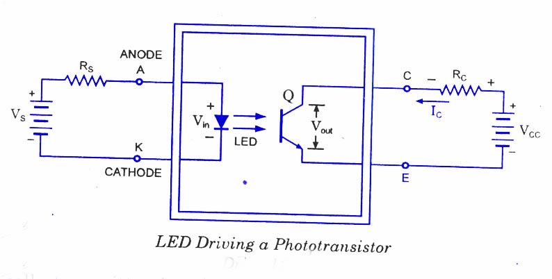
A lot of electronic equipment nowadays is using opt coupler in the circuit. An opt coupler or sometimes refer to as opt isolator allows two circuits to exchange signals yet remain electrically isolated. This is usually accomplished by using light   to relay the signal. The standard opt coupler circuits design uses a LED shining on a phototransistor-usually it is a npn transistor and not pnp. The signal is applied to the LED, which then shines on the transistor in the IC.
The light is proportional to the signal, so the signal is thus transferred to the photo-transistor. Opt couplers may also comes in few module such as the SCR, photodiodes, TRIAC of other semiconductor switch as an output, and incandescent lamps, neon bulbs or other light source.
Most commonly used is an opto-coupler MOC3021 an LED diac type combination. This IC is interfaced with a microcontroller and an LED is connected in series to the IC, which glows to indicate a logic High pulse from the microcontroller so that we can know that current is flowing in internal LED of the opto-IC. When logic high is given current flows through LED from pin1 to 2. So in this process LED light falls on DIAC causing 6 & 4 to close. During each half cycle current flows through gate, series resistor and through opto-diac for the main thyristor / triac to trigger for the load to operate.
The opto coupler usually found in switch mode power supply circuit in many electronic equipment. It is connected in between the primary and secondary section of power supplies. The opto-coupler application or function in the circuit is to:
  1. Monitor high voltage
  2. Output voltage sampling for regulation
  3. System control micro for power ON/OFF
  4. Ground isolation
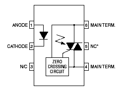
This is the principle used in Opto−Diacs, the Opto-Diacs are available in form of ICs and can be implemented using a simple circuitry.
Simply provide a small pulse at the right time to the Light Emitting Diode in the package. The light produced by the LED activates the light sensitive properties of the diac and the power is switched on. The isolation between the low power and high power circuits in these optically connected devices is typically several thousand volts.

Opto-Diacs Pin Description:

Opto-Diacs

4 Different Opto Couplers available

1. MOC3020

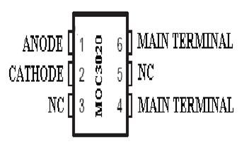
It comes in 6-pin DIP is shown in figure:
MOC3020

Working Principle of MOC3020:

The MOC3020 are designed for interfacing between electronic controls and power triac to control resistive and inductive loads for Vac operations. The principle used in opto-coupler is, MOC’s are promptly available in integrated circuit form and don’t require very complex circuitry to make them work. Simply give a small pulse at the right time to the LED in the package. The light produced by the LED activates the light sensitive properties of the diac and the power is switched on. The isolation between the low power and high power circuits in these optically connected devices is typically few thousand volts.

Features of MOC3020:

  • 400 V Photo-TRIAC Driver Output
  • Gallium-Arsenide-Diode infrared source and optically-coupled silicon triac driver
  • High isolation – 500 Vpeak
  • Output driver designed for 220 Vac
  • Standard 6-terminal plastic DIP
  • Directly interchangeable with Motorola MOC3020, MOC3021 and MOC3022

 Typical applications of MOC3020:

  • Solenoid/valve controls
  • Lamp ballasts
  • Interfacing microprocessors to 115/240 Vac peripherals
  • Motor controls
  • Incandescent lamp dimmers

 Application of MOC3020:

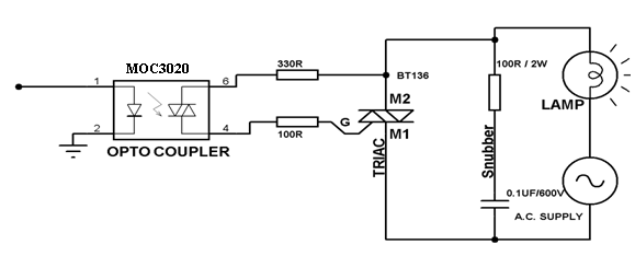
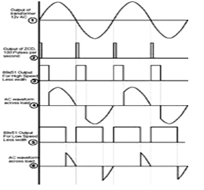
The circuit shown below is a typical circuit used for AC load control from microcontroller, one LED can be connected in series with MOC3021, LED to indicate when high is given from micro controller such that we can know that current is flowing in internal LED of the opto-coupler.The idea is to use a power lamp whose activation requires mains AC as opposed to a DC voltage. That’s way, the mains AC power that we’re trying to switch the lamp and no external power supply is required. To switch the AC current to the lamp, we have to use an opto-coupled triac, lamp and a diac is shown in circuit below. A triac is said to be as an AC controlled switch. It has three terminals M1, M2 and gate. A TRIAC, lamp load and a supply voltage are connected in series. When supply is ON at positive cycle then the current flows through lamp, resistors, diac, and gate and reaches the supply and then only lamp glows for that half cycle directly through the M2 and M1 terminal of the triac. In negative half cycle the same thing repeats. Thus the lamp glows in both the cycles in a controlled manner depending upon the triggering pulses at the opto isolator as seen on the graph below. If this is given to a motor instead of lamp the power is controlled resulting in speed control.
MOC3020 cir
MOC3020 circuit

 2. MOC3021

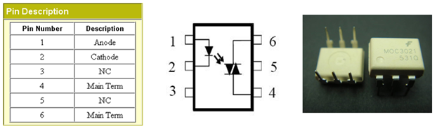
MOC3021 is an opto-coupler designed for triggering TRIACS. By using this we can trigger anywhere in the cycle, so can call them as non-zero opto-coupler. MOC3021 are very widely used and can be quite easily obtained from many sources. It comes in 6-pin DIP shown in figure.

Pin Description:

Pin 1: Anode
Pin 2: Cathode
Pin 3: No connection (NC)
Pin 4: Main terminal
Pin 5: No connection (NC)
Pin 6: Main terminal

Features:

  • 400 V Photo-triac driver output
  • Gallium-Arsenide-Diode Infrared Source and Optically-Coupled Silicon triac driver
  • High Isolation 7500 V Peak
  • Output Driver Designed for 220 Vac
  • Standard 6-terminal plastic DIP
There are many applications of MOC3021 such as solenoid/valve controls, lamp ballasts, interfacing microprocessors to 115/240 Vac peripherals, motor controls and incandescent lamp dimmers.

Application of MOC3021:

From the below circuit, the most commonly used is an opto-coupler MOC3021 with an LED diac type combination. Additionally while using this with microcontroller and one LED can be connected in series with MOC3021, LED to indicate when high is given from micro controller such that we can know that current is flowing in internal LED of the opto-coupler. When logic high is given then the current flows through the LED from pin 1 to 2. So in this process LED light falls on DIAC causing 6 and 4 to close. During each half cycle current flows through gate, series resistor and through opto-diac for the main thyristor / triac to trigger for the load to operate.

3. MCT2E

The MCT2E series of opto-coupler devices each consist of gallium arsenide infrared LED and a silicon NPN phototransistor. They are packaged in a 6-pin DIP package and available in wide-lead spacing.
Pin 1: Anode.
Pin 2: Cathode.
Pin 3: No connection.
Pin 4: Emitter.
Pin 5: Collector.
Pin 6: Base.

Features:

  • Isolation test voltage 5000 VRMS
  • Interfaces with common logic families
  • Input-output coupling capacitance < 0.5 pF
  • Industry standard dual-in-line 6 pin package
  • Compliant to RoHS directive 2002/95/EC
The opto-coupler usually found in switch mode power supply circuit, read relay driving, industrial controls, digital logic inputs and in many electronic equipments

Application of MCT2E:

It is a combination of 1 LED and a transistor. Pin 6 of transistor is not generally used and when light falls on the base-emitter junction then it switches and pin5 goes to zero.
  • When logic zero is given as input then the light doesn’t fall on transistor so it doesn’t conduct which gives logic one as output.
  • When logic 1 is given as input then light falls on transistor so that it conducts, that makes transistor switched ON and it forms short circuit this makes the output is logic zero as collector of transistor is connected to ground.

4. MOC363

The MOC3063 devices consist of gallium arsenide infrared emitting diodes optically coupled to monolithic silicon detectors performing the functions of zero voltage crossing bilateral triac drivers. It is also a 6-pin DIP shown in figure:
MOC3063

Pin Description:

Pin 1: Anode
Pin 2: Cathode
Pin 3: No connection (NC)
Pin 4: Main terminal
Pin 5: No connection (NC)
Pin 6: Main terminal

Features:

  • Simplifies logic control of 115/240 Vac power
  • Zero crossing voltage
  • dv/dt of 1500 V/µs typical, 600 V/µs guaranteed
  • VDE recognized
  • Underwriters Laboratories (UL) recognized

Applications:

  • Solenoid/valve controls
  • Static power switches
  • Temperature controls
  • AC motor starters and drivers
  • Lighting controls
  • E.M. contactors
  • Solid state relay

 Working of MOC3063:

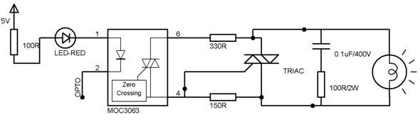
From the circuit, we have an opto-coupler MOC3063 with an LED SCR type combination. Additionally while using this opto-coupler with microcontroller and one LED can be connected in series with MOC3063 LED to indicate when high is given from micro controller such that we can know that current is flowing in internal LED of the opto-coupler. When logic high is given then the current flows through LED from pin 1 to 2. The LED light falls on SCR causing 6 and 4 to close only at the zero cross of the supply voltage. During each half cycle current flows through SCR gate, external series resistor and through SCR for the main thyristor/triac to trigger for the load at the beginning of the supply cycle always to operate.
MOC3063-circuit

Optocoupler Characteristics, Types and Application

Optocoupler Characteristics, Types and Application

We know from our tutorials about Transformers that they not only provide higher or lower voltage differences between their primary and secondary windings, but they also provide “electrical isolation” between the higher voltages on the primary side and the lower voltage on the secondary side.
In other words, transformers isolate the primary input voltage from the secondary output voltage using electromagnetic coupling by means of a magnetic flux circulating within the iron laminated core. But we can also provide electrical isolation between an input source and an output load using just light by using a very common and valuable electronic component called an Optocoupler.
typical 4n35 optocoupler
An Optocoupler, also known as an Opto-isolator or Photo-coupler, is an electronic components that interconnects two separate electrical circuits by means of a light sensitive optical interface.
The basic design of an Optocoupler consists of an LED that produces infra-red light and a semiconductor photo-sensitive device that is used to detect the emitted infra-red beam. Both the LED and photo-sensitive device are enclosed in a light-tight body or package with metal legs for the electrical connections as shown.
An optocoupler or opto-isolator consists of a light emitter, the LED and a light sensitive receiver which can be a single photo-diode, photo-transistor, photo-resistor, photo-SCR, or a photo-TRIAC and the basic operation of an optocoupler is very simple to understand.

Phototransistor Optocoupler

phototransistor optocoupler
Assume a photo-transistor device as shown. Current from the source signal passes through the input LED which emits an infra-red light whose intensity is proportional to the electrical signal.
This emitted light falls upon the base of the photo-transistor, causing it to switch-ON and conduct in a similar way to a normal bipolar transistor.
The base connection of the photo-transistor can be left open for maximum sensitivity or connected to ground via a suitable external resistor to control the switching sensitivity making it more stable.
When the current flowing through the LED is interrupted, the infra-red emitted light is cut-off, causing the photo-transistor to cease conducting. The photo-transistor can be used to switch current in the output circuit. The spectral response of the LED and the photo-sensitive device are closely matched being separated by a transparent medium such as glass, plastic or air. Since there is no direct electrical connection between the input and output of an optocoupler, electrical isolation up to 10kV is achieved.
Optocouplers are available in four general types, each one having an infra-red LED source but with different photo-sensitive devices. The four optocouplers are called the: Photo-transistorPhoto-darlingtonPhoto-SCR and Photo-triac as shown below.

Optocoupler Types

optocoupler types
The photo-transistor and photo-darlington devices are mainly for use in DC circuits while the photo-SCR and photo-triac allow AC powered circuits to be controlled. There are many other kinds of source-sensor combinations, such as LED-photodiode, LED-LASER, lamp-photoresistor pairs, reflective and slotted optocouplers.
Simple homemade optocouplers can be constructed by using individual components. An Led and a photo-transistor are inserted into a rigid plastic tube or encased in heat-shrinkable tubing as shown. The advantage of this home-made optocoupler is that tubing can be cut to any length you want and even bent around corners. Obviously, tubing with a reflective inner would be more efficient than dark black tubing.

Home-made Optocoupler

home made optocoupler

Optocoupler Applications

Optocouplers and opto-isolators can be used on their own, or to switch a range of other larger electronic devices such as transistors and triacs providing the required electrical isolation between a lower voltage control signal and the higher voltage or current output signal. Common applications for optocouplers include microprocessor input/output switching, DC and AC power control, PC communications, signal isolation and power supply regulation which suffer from current ground loops, etc. The electrical signal being transmitted can be either analogue (linear) or digital (pulses).
In this application, the optocoupler is used to detect the operation of the switch or another type of digital input signal. This is useful if the switch or signal being detected is within an electrically noisy environment. The output can be used to operate an external circuit, light or as an input to a PC or microprocessor.

An Optotransistor DC Switch

optotransistor switch
As well as detecting DC signals and data, Opto-triac isolators are also available which allow AC powered equipment and mains lamps to be controlled. Opto-coupled triacs such as the MOC 3020, have voltage ratings of about 400 volts making them ideal for direct mains connection and a maximum current of about 100mA. For higher powered loads, the opto-triac may be used to provide the gate pulse to another larger triac via a current limiting resistor as shown.

Triac Optocoupler Application

triac optocoupler application
This type of optocoupler configuration forms the basis of a very simple solid state relay application which can be used to control any AC mains powered load such as lamps and motors. Also unlike a thyristor (SCR), a triac is capable of conducting in both halves of the mains AC cycle with zero-crossing detection allowing the load to receive full power without the heavy inrush currents when switching inductive loads.
Optocouplers and Opto-isolators are great electronic devices that allow devices such as power transistors and triacs to be controlled from a PC’s output port, digital switch or from a low voltage data signal such as that from a logic gate. The main advantage of opto-couplers is their high electrical isolation between the input and output terminals allowing relatively small digital signals to control much large AC voltages, currents and power.
An optocoupler can be used with both DC and AC signals with optocouplers utilizing a SCR (thyristor) or triac as the photo-detecting device are primarily designed for AC power-control applications. The main advantage of photo-SCRs and photo-triacs is the complete isolation from any noise or voltage spikes present on the AC power supply line as well as zero-crossing detection of the sinusoidal waveform which reduces switching and inrush currents protecting any power semiconductors used from thermal stress and shock.
Characteristics of an Optocoupler: 
  
optocoupler-characteristics

  
Current Transfer Ratio (CTR). One of the most important parameters of an optocoupler device is its optocoupling efficiency. This parameter is maximized by closely matching spectrally the LED and the phototransistor (which usually operate in the infra-red range). The optocoupling efficiency of an optocoupler may be conveniently specified by the output-to-input current transfer ratio (CTR) i.e., the ratio of the output current Ic (measured at the collector terminal of the phototransistor), to the input current IF flowing into the LED. 
Input-to-Output Isolation Voltage (Viso). This is the maximum potential difference (dc) that can be allowed to exist between the input and output terminals. Typical values range from 500 V to 4 kV. 
Maximum Collector-Emitter Voltage, VCE (max). This is the maximum allowable dc voltage that can be applied across the output transistor. Typical values may vary from 20 to 80 volts.  
Bandwidth. This is the typical maximum signal frequency (in kHz) that can be use­fully passed through the optocoupler when the device is operated in its normal mode. Typical values vary from 20 to 500 kHz, depending on the type of device construction. 
Response Time. Divided into rise time tr and fall time t*. For a phototransistor output stages, tr andtr are usually around 2 to 5 us. 
simple isolating optocoupler uses a single phototransistor output stage and is usually housed in a six-pin package, with the base terminal of the phototransistor externally available. In nor­mal use the base is left open circuit, and under such a condition the optocoupler has a minimum CTR value of 20 % and a useful bandwidth of 300 kHz. 

Monday, March 14, 2016

Use of MPPT in CONSTANT VOLTAGE output boast converter in MATLAB


What is MAXIMUM POWER Point ??

This section covers the theory and operation of "Maximum Power Point Tracking" as used in solar electric charge controllers.
A MPPT, or maximum power point tracker is an electronic DC to DC converter that optimizes the match between the solar array (PV panels), and the battery bank or utility grid. To put it simply, they convert a higher voltage DC output from solar panels (and a few wind generators) down to the lower voltage needed to charge batteries.
(These are sometimes called "power point trackers" for short - not to be confused with PANEL trackers, which are a solar panel mount that follows, or tracks, the sun).

So what do you mean by "optimize"?

Solar cells are neat things. Unfortunately, they are not very smart. Neither are batteries - in fact batteries are downright stupid. Most PV panels are built to put out a nominal 12 volts. The catch is "nominal". In actual fact, almost all "12 volt" solar panels are designed to put out from 16 to 18 volts. The problem is that a nominal 12 volt battery is pretty close to an actual 12 volts - 10.5 to 12.7 volts, depending on state of charge. Under charge, most batteries want from around 13.2 to 14.4 volts to fully charge - quite a bit different than what most panels are designed to put out.
OK, so now we have this neat 130 watt solar panel. Catch #1 is that it is rated at 130 watts at a particular voltage and current. The Kyocera KC-130 is rated at 7.39 amps at 17.6 volts. (7.39 amps times 17.6 volts = 130 watts).

Now the Catch 22

Why 130 Watts does NOT equal 130 watts

Where did my Watts go?

So what happens when you hook up this 130 watt panel to your battery through a regular charge controller?

Unfortunately, what happens is not 130 watts.

Your panel puts out 7.4 amps. Your battery is setting at 12 volts under charge: 7.4 amps times 12 volts = 88.8 watts. You lost over 41 watts - but you paid for 130. That 41 watts is not going anywhere, it just is not being produced because there is a poor match between the panel and the battery. With a very low battery, say 10.5 volts, it's even worse - you could be losing as much as 35% (11 volts x 7.4 amps = 81.4 watts. You lost about 48 watts.
One solution you might think of - why not just make panels so that they put out 14 volts or so to match the battery?
Catch #22a is that the panel is rated at 130 watts at full sunlight at a particular temperature (STC - or standard test conditions). If temperature of the solar panel is high, you don't get 17.4 volts. At the temperatures seen in many hot climate areas, you might get under 16 volts. If you started with a 15 volt panel (like some of the so-called "self regulating" panels), you are in trouble, as you won't have enough voltage to put a charge into the battery. Solar panels have to have enough leeway built in to perform under the worst of conditions. The panel will just sit there looking dumb, and your batteries will get even stupider than usual.
Nobody likes a stupid battery.

WHAT IS MAXIMUM POWER POINT TRACKING?

There is some confusion about the term "tracking":
Panel tracking - this is where the panels are on a mount that follows the sun. The most common are the Zomeworks and Wattsun. These optimize output by following the sun across the sky for maximum sunlight. These typically give you about a 15% increase in winter and up to a 35% increase in summer. 
This is just the opposite of the seasonal variation for MPPT controllers. Since panel temperatures are much lower in winter, they put out more power. And winter is usually when you need the most power from your solar panels due to shorter days.
Maximum Power Point Tracking is electronic tracking - usually digital. The charge controller looks at the output of the panels, and compares it to the battery voltage. It then figures out what is the best power that the panel can put out to charge the battery. It takes this and converts it to best voltage to get maximum AMPS into the battery. (Remember, it is Amps into the battery that counts). Most modern MPPT's are around 93-97% efficient in the conversion. You typically get a 20 to 45% power gain in winter and 10-15% in summer. Actual gain can vary widely depending weather, temperature, battery state of charge, and other factors.
Grid tie systems are becoming more popular as the price of solar drops and electric rates go up. There are several brands of grid-tie only (that is, no battery) inverters available. All of these have built in MPPT. Efficiency is around 94% to 97% for the MPPT conversion on those.

How Maximum Power Point Tracking works

Here is where the optimization, or maximum power point tracking comes in. Assume your battery is low, at 12 volts. A MPPT takes that 17.6 volts at 7.4 amps and converts it down, so that what the battery gets is now 10.8 amps at 12 volts. Now you still have almost 130 watts, and everyone is happy.
Ideally, for 100% power conversion you would get around 11.3 amps at 11.5 volts, but you have to feed the battery a higher voltage to force the amps in. And this is a simplified explanation - in actual fact the output of the MPPT charge controller might vary continually to adjust for getting the maximum amps into the battery.
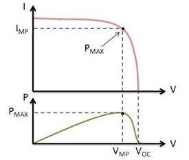
On the left is a screen shot from the Maui Solar Software "PV-Design Pro" computer program (click on picture for full size image). If you look at the green line, you will see that it has a sharp peak at the upper right - that represents the maximum power point. What an MPPT controller does is "look" for that exact point, then does the voltage/current conversion to change it to exactly what the battery needs. In real life, that peak moves around continuously with changes in light conditions and weather.
A MPPT tracks the maximum power point, which is going to be different from the STC (Standard Test Conditions) rating under almost all situations. Under very cold conditions a 120 watt panel is actually capable of putting over 130+ watts because the power output goes up as panel temperature goes down - but if you don't have some way of tracking that power point, you are going to lose it. On the other hand under very hot conditions, the power drops - you lose power as the temperature goes up. That is why you get less gain in summer.
MPPT's are most effective under these conditions:
Winter, and/or cloudy or hazy days - when the extra power is needed the most.
  • Cold weather - solar panels work better at cold temperatures, but without a MPPT you are losing most of that. Cold weather is most likely in winter - the time when sun hours are low and you need the power to recharge batteries the most.
  • Low battery charge - the lower the state of charge in your battery, the more current a MPPT puts into them - another time when the extra power is needed the most. You can have both of these conditions at the same time.
  • Long wire runs - If you are charging a 12 volt battery, and your panels are 100 feet away, the voltage drop and power loss can be considerable unless you use very large wire. That can be very expensive. But if you have four 12 volt panels wired in series for 48 volts, the power loss is much less, and the controller will convert that high voltage to 12 volts at the battery. That also means that if you have a high voltage panel setup feeding the controller, you can use much smaller wire.
Ok, so now back to the original question - What is a MPPT?

How a Maximum Power Point Tracker Works:

The Power point tracker is a high frequency DC to DC converter. They take the DC input from the solar panels, change it to high frequency AC, and convert it back down to a different DC voltage and current to exactly match the panels to the batteries. MPPT's operate at very high audio frequencies, usually in the 20-80 kHz range. The advantage of high frequency circuits is that they can be designed with very high efficiency transformers and small components. The design of high frequency circuits can be very tricky because the problems with portions of the circuit "broadcasting" just like a radio transmitter and causing radio and TV interference. Noise isolation and suppression becomes very important.
There are a few non-digital (that is, linear) MPPT's charge controls around. These are much easier and cheaper to build and design than the digital ones. They do improve efficiency somewhat, but overall the efficiency can vary a lot - and we have seen a few lose their "tracking point" and actually get worse. That can happen occasionally if a cloud passed over the panel - the linear circuit searches for the next best point, but then gets too far out on the deep end to find it again when the sun comes out. Thankfully, not many of these around any more.
The power point tracker (and all DC to DC converters) operates by taking the DC input current, changing it to AC, running through a transformer (usually a toroid, a doughnut looking transformer), and then rectifying it back to DC, followed by the output regulator. In most DC to DC converters, this is strictly an electronic process - no real smarts are involved except for some regulation of the output voltage. Charge controllers for solar panels need a lot more smarts as light and temperature conditions vary continuously all day long, and battery voltage changes.

Smart power trackers

All recent models of digital MPPT controllers available are microprocessor controlled. They know when to adjust the output that it is being sent to the battery, and they actually shut down for a few microseconds and "look" at the solar panel and battery and make any needed adjustments. Although not really new (the Australian company AERL had some as early as 1985), it has been only recently that electronic microprocessors have become cheap enough to be cost effective in smaller systems (less than 1 KW of panel). MPPT charge controls are now manufactured by several companies, such as Outback Power, Xantrex XW-SCC, Blue Sky Energy, Apollo Solar, Midnite Solar, Morningstar and a few others.

What is the difference between Socket and Port?

Socket Sockets allow communication between two different processes on the same or different machines. To be more precise, it's a way to ...