Monday, February 1, 2016

Parks Transformation

Dq0 Transform

The dq0 transform (often called the Park transform) is a space vector transformation of three-phase time-domain signals from a stationary phase coordinate system (ABC) to a rotating coordinate system (dq0).
The transform applied to time-domain voltages in the natural frame (i.e. uaub and uc) is as follows:
\begin{bmatrix} u_{d} \\ u_{q} \\ u_{0} \end{bmatrix} = \frac{2}{3}\begin{bmatrix} \cos(\theta)&\cos(\theta - \frac{2\pi}{3})&\cos(\theta + \frac{2\pi}{3}) \\
 - \sin(\theta)& - \sin(\theta - \frac{2\pi}{3})& - \sin(\theta + \frac{2\pi}{3}) \\
\frac{1}{2}& \frac{1}{2} & \frac{1}{2} \end{bmatrix}\begin{bmatrix}u_a\\u_b\\u_c\end{bmatrix}
Where  \theta = \omega t + \delta_{A} \,  is the angle between the rotating and fixed coordinate system at each time t and  \delta_{A} \,  is an initial phase shift of the voltage.
The inverse transformation from the dq0 frame to the natural abc frame:
\begin{bmatrix} u_{a} \\ u_{b} \\ u_{c} \end{bmatrix} = \begin{bmatrix}\cos(\theta)& - \sin(\theta)& 1 \\
\cos(\theta - \frac{2\pi}{3})& - \sin(\theta - \frac{2\pi}{3})& 1 \\
\cos(\theta + \frac{2\pi}{3})& - \sin(\theta + \frac{2\pi}{3})& 1 \end{bmatrix}
\begin{bmatrix}u_d\\u_q\\u_o\end{bmatrix}
As in the Clarke Transform, it is interesting to note that the 0-component above is the same as the zero sequence component in the symmetrical components transform. For example, for voltages Ua, Ub and Uc, the zero sequence component for both the dq0 and symmetrical components transforms is  \frac{1}{3} \left( U_{a} + U_{b} + U_{c} \right) .
The remainder of this article provides some of the intuition behind why the dq0 transform is so useful in electrical engineering.

The dq0 transform is essentially an extension of the Clake transform, applying an angle transformation to convert from a stationary reference frame to a synchronously rotating frame. The synchronous reference frame can be aligned to rotate with the voltage (e.g. used in voltage source converters) or with the current (e.g. used in current source converters).
Quadrature stationary and rotating reference frames
Historically however, the dq0 transform was introduced earlier than the Clarke transform by R. H. Park in his seminal 1929 paper on synchronous machine modelling [1].

Classical dq0 Transform in Balanced Systems


dq0 Transform of Balanced Three-Phase Voltages

The following equations take a two-phase quadrature voltage along the stationary frame and transforms it into a two-phase synchronous frame (with a reference frame aligned to the voltage):
\begin{bmatrix} u_{d} \\ u_{q} \\ u_{0} \end{bmatrix}  = \begin{bmatrix}  \cos{\theta} & \sin{\theta} & 0 \\ 
-\sin{\theta} & \cos{\theta} & 0 \\ 0 & 0 & 1 \\ \end{bmatrix} \begin{bmatrix} u_{\alpha} \\ u_{\beta} \\ u_{0} \end{bmatrix}
Note that in the dq0 frame, the 0-component is the same as that in the \alpha \beta 0 \,  frame. Moreover, as we saw in the Clarke transform, the 0-component is zero for balanced three-phase systems. Therefore in the following discussion on balanced systems, the 0-component will be omitted.
Consider a balanced three-phase voltage with \alpha \beta 0 \,  components as follows:
\begin{bmatrix} u_{\alpha} \\ u_{\beta} \\ u_{0} \\ \end{bmatrix} = \begin{bmatrix} 
U_{m} \cos(\omega t)  \\ 
U_{m} \sin(\omega t) \\ 
0  \\ 
\end{bmatrix}
The dq0 transform of this voltage is:
\begin{bmatrix} u_{d} \\ u_{q} \\ \end{bmatrix}  = \begin{bmatrix}  \cos{\theta} & \sin{\theta} \\ 
-\sin{\theta} & \cos{\theta} \\ \end{bmatrix} \begin{bmatrix} u_{\alpha} \\ u_{\beta} \\ \end{bmatrix}
Suppose that we are using a voltage reference frame and will align the synchronous frame with the voltage. Therefore  \theta = \omega t \,  and:
\begin{bmatrix} u_{d} \\ u_{q} \\ \end{bmatrix}  = \begin{bmatrix} U_{m} \sin{\omega t} \sin(\omega t) + U_{m} \cos{\omega t} \cos(\omega t) \\ 
U_{m} \cos{\omega t} \sin(\omega t) - U_{m} \sin{\omega t} \cos(\omega t) \\ \end{bmatrix}
= \begin{bmatrix} U_{m} \\ 0 \\ \end{bmatrix}
It can be observed that since the synchronous frame is aligned to rotate with the voltage, the d-component corresponds to the magnitude of the voltage and the q-component is zero. A plot of the transformation of a voltage from a stationary αβ frame into rotating dq frame is shown in the figure below.
Results of dq0 transform of voltage giving two dc components
The inverse transform is as follows:
\begin{bmatrix} u_{\alpha} \\ u_{\beta} \\ \end{bmatrix}  = \begin{bmatrix}  \cos{\theta} & -\sin{\theta} \\ 
\sin{\theta} & \cos{\theta} \\ \end{bmatrix} \begin{bmatrix} u_{d} \\ u_{q} \\ \end{bmatrix}

dq0 Transform of Balanced Three-Phase Currents

The dq0 transformation can be similarly applied to the current. From a two-phase quadrature stationary (αβ0) current of the form (where δ is the angle at which the current lags the voltage):
\begin{bmatrix} I_{\alpha} \\ I_{\beta} \\ I_{0} \\ \end{bmatrix} = \begin{bmatrix} 
I_{m} \cos(\omega t - \delta)  \\ 
I_{m} \sin(\omega t - \delta) \\ 
0  \\ 
\end{bmatrix}
We transform it into a two-phase synchronous (dq0) frame:
\begin{bmatrix} i_{d} \\ i_{q} \\ \end{bmatrix}  = \begin{bmatrix}  \cos{\theta} & \sin{\theta} \\ 
-\sin{\theta} & \cos{\theta} \\ \end{bmatrix} \begin{bmatrix} i_{\alpha} \\ i_{\beta} \\ \end{bmatrix}
 = \begin{bmatrix}  \cos{\theta} & \sin{\theta} \\ 
-\sin{\theta} & \cos{\theta} \\ \end{bmatrix} \begin{bmatrix} I_{m} \sin(\omega t - \delta) \\ I_{m} \cos(\omega t - \delta) \\ \end{bmatrix}
 = \begin{bmatrix} I_{m} \cos(\delta) \\ -I_{m} \sin(\delta) \\ \end{bmatrix}
Results of dq0 transform of current giving two dc components

Instantaneous Power in dq0 Frame

The instantaneous active and reactive power from a set of two-phase (dq) voltages and currents are:
p = u_{d} i_{d} + u_{q} i_{q} \,
q = u_{q} i_{d} - u_{d} i_{q} \,
When the synchronous frame is aligned to voltage, we saw earlier that the quadrature component : u_{q} = 0 \, . Therefore, the power equations reduce to:
p = u_{d} i_{d} \,
q = - u_{d} i_{q} \,
The above equations show that independent control of active and reactive power is possible by means of controlling the dq current components (id and iq).

Summary of dq0 Transform in Balanced Systems

For three-phase balanced systems, the dq0 transform has the following advantageous characteristics:
1) The dq0 transform reduces three-phase AC quantities (e.g. uaub and uc) into two DC quantities (e.g. uduq). For balanced systems, the 0-component is zero. The DC quantities facilitate easier filtering and control.
2) Active and reactive power can be controlled independently by controlling the dq components.

Power Invariant Formulation

The classical Park transform is not power invariant, i.e. the instantaneous power of the variables calculated in the dq0 frame is not the same as the power calculated in the natural coordinate reference frame. A power invariant version of the dq0 transform is as follows:
\begin{bmatrix} u_{d} \\ u_{q} \\ u_{0} \end{bmatrix} = \sqrt{\frac{2}{3}}\begin{bmatrix} \cos(\theta)&\cos(\theta - \frac{2\pi}{3})&\cos(\theta + \frac{2\pi}{3}) \\
 - \sin(\theta)& - \sin(\theta - \frac{2\pi}{3})& - \sin(\theta + \frac{2\pi}{3}) \\
\frac{1}{\sqrt{2}}& \frac{1}{\sqrt{2}} & \frac{1}{\sqrt{2}} \end{bmatrix}\begin{bmatrix}u_a\\u_b\\u_c\end{bmatrix}
Inverse transform:
\begin{bmatrix} u_{a} \\ u_{b} \\ u_{c} \end{bmatrix} = \sqrt{\frac{2}{3}}\begin{bmatrix}\cos(\theta)& - \sin(\theta)&\frac{\sqrt{2}}{2}\\
\cos(\theta - \frac{2\pi}{3})& - \sin(\theta - \frac{2\pi}{3})&\frac{\sqrt{2}}{2}\\
\cos(\theta + \frac{2\pi}{3})& - \sin(\theta + \frac{2\pi}{3})&\frac{\sqrt{2}}{2}\end{bmatrix}
\begin{bmatrix}u_d\\u_q\\u_o\end{bmatrix}
REF:wikipedia

UNDERSTANDING POWER FLOW IN AC SYSTEM

Understanding AC power.

A whole house energy monitor measures the energy used by appliances connected to the house mains. To understand how it does this, it is useful to know something about how appliances interact with the electrical system.
Not all appliances interact with the electricity system in the same way. This article will first discuss resistive loads and how the power they use is calculated. It then goes on to discuss reactive loads, and a bit about non-linear loads. Finally, it will show how we measure the direction of power flow, which is important if energy is  generated as well as consumed.
Resistive loads
Incandescent light bulbs, kettles, irons, electric water heaters, electric cookers are all quite straightforward. They use all the energy given to them. They are resistive loads which means their current draw is equal to the voltage divided by their resistance (Ohms Law). A purely resistive load gives a voltage and current waveform output similar to the following:

Diagram 1 – Voltage and current phase relationships in a resistive load
The yellow line is power at a given time (at any given instant it's called instantaneous power) which is equal to the product of the voltage and current at a given time. Notice the power is always positive. In this case, the positive direction is energy flowing to the load.
Partially reactive loads
However things like fridges, washing machines, pillar drills and arc welders are not so straightforward as these appliances take in a certain amount of energy, then release some energy back into the mains supply. These have inductive (e.g. motors) or capacitive (e.g. arc welders) components in addition to the resistive component. A partially inductive load gives a voltage and current waveform output similar to the following:

Diagram 2 – Voltage and current phase relationships in a partially reactive load
Notice the yellow line now goes negative for a period of time, the positive bit is energy flowing to the load and the negative bit is energy flowing back from the load.
The other thing to consider is that the voltage and current waveforms have been shifted apart. Imagine charging a fairly large capacitor with a resistor in series (so that it can't charge instantly): To start with, the capacitor is discharged. The supply voltage rises, and is higher than the voltage on the capacitor, so current flows into the capacitor (the positive direction on the graph), which causes the capacitor voltage to rise. The supply voltage falls. Now, the voltage across the charged capacitor is higher than the supply voltage. Current starts to flow back in the direction of the supply (the negative direction on the graph). This causes the current waveform to appear as if it is shifted, as depicted in the graph. (This is referred to as phase shift).
Real Power, Reactive power and Apparent Power.
Looking at the voltage, current and power graphs above at mains frequency the power draw fluctuates 50/60 times a second. We cant keep up with change at this speed, so we have a more useful value for power: the average of the instantaneous power, which we call real or active power.
Real power is often defined as the power used by a device to produce useful work. Referring to the graph above, the positive bits are power going to the load from the supply, and the negative bits are power going back to the supply, from the load. The power that was actually used by the load, i.e. the power going to, minus the power going back, is the real power.
Reactive or imaginary power, is a measure of the power going back and forth between the load and the supply that does no useful work.
Another useful measure of power is Apparent Power, which is the product of the Root-Mean-Square (RMS) Voltage and the RMS Current. For purely resistive loads, real power is equal to apparent power. But for all other loads, real power is less than apparent power. Apparent power is a measure of the real and reactive power, but it is not a sum of the two, as the sum of the two does not take into account phase differences.
Relationship between real, reactive and apparent power for IDEAL sinusoidal loads:
Real Power = Apparent Power x cosΦ
Reactive Power = Apparent Power x sinΦ
cosΦ is also known as power factor.
However a note about non-linear loads:
This power factor relationship is valid only for linear sinusoidal loads. Most power supplies for DC devices like Laptop computers, present a non-linear load to the mains. Their current draw often looks like this:
We can still calculate power factor from the following equation:
Power Factor = Real Power / Apparent Power
but the relationship
(Apparent Power)2 = (Real Power)2 + (Reactive Power)2
which is true for pure sine waves, is no longer correct. Neither is power factor = cosΦ, since the effects of higher order harmonics in both voltage and current waveforms must be considered.
The power factor value measures how much the mains efficiency is affected by BOTH phase lag φ AND harmonic content of the input current.

Determining the direction of power flow.

Until now, this article has assumed that the load is consuming power. If however, we are generating power, then the direction the current flows is reversed. But because the current is alternating, the direction is reversing anyway, 50 (or 60) times each second. We need a reference to compare the current direction against. Fortunately, we have that in the form of the voltage. In diagram 1, the voltage and current waves both rose and fell together. When the voltage was positive (above the X axis) the current was positive, and when the voltage was negative (below the x axis) the current was negative. Power is equal to the product of the voltage and current, and so the power was always positive - all of the power curve is above the X axis.
If the house is generating power, the direction of the current is reversed compared to our previous example. Now when the voltage is positive, (above the X axis) the current is negative (below the X axis), and when the voltage is negative, the current is positive. The power always negative - all of the power curve is below the X axis.

Diagram 4 – Voltage and current phase relationships when generating energy.
The sign of the power therefore indicates whether power is being consumed or generated.
To sum up
There are many parameters we can measure regarding energy use in AC systems. Each one has its merits. For the household energy metering, real power is likely to be the most useful value, as it is tells you how much power all your appliances are actually consuming, and it is what the utility bills you for.

Wednesday, January 6, 2016

what is adaptive protection?


The use of adjustable protective relay settings (e.g., current, voltage, feeders, and equipment) that can change in real time based on signals from local sensors or a central control system. This is particularly useful for feeder transfers and two-way power flow issues associated with high Distributed Energy Resource (DER) penetration.

ANSI/IEEE Standard Device Numbers

Power Systems Protection and Relaying Fall 2014
ANSI/IEEE Standard Device Numbers

In North America protective relays are generally referred to by standard device numbers. Letters
are sometimes added to specify the application (IEEE Standard C37.2-2008).

Device Numbers (the more commonly used ones are in bold)

1 - Master Element
2 - Time Delay Starting or Closing Relay
3 - Checking or Interlocking Relay
4 - Master Contactor
5 - Stopping Device
6 - Starting Circuit Breaker
7 – Rate of Change Relay
8 - Control Power Disconnecting Device
9 - Reversing Device
10 - Unit Sequence Switch
11 – Multifunction Device
12 - Overspeed Device
13 - Synchronous-speed Device
14 - Underspeed Device
15 - Speed or Frequency-Matching Device
16 – Data Communications Device
20 - Elect. operated valve (solenoid valve)
21 - Distance Relay
23 - Temperature Control Device
24 – Volts per Hertz Relay
25 - Synchronizing or Synchronism-Check
Device
26 - Apparatus Thermal Device
27 - Undervoltage Relay
30 - Annunciator Relay
32 - Directional Power Relay
36 - Polarity or Polarizing Voltage Devices
37 - Undercurrent or Underpower Relay
38 - Bearing Protective Device
39 - Mechanical Conduction Monitor
40 –Field (over/under excitation) Relay
41 - Field Circuit Breaker
42 - Running Circuit Breaker
43 - Manual Transfer or Selector Device
46 – Rev. phase or Phase-Bal. Current Relay
47 - Phase-Seq. or Phase-Bal. Voltage Relay
48 - Incomplete-Sequence Relay
49 - Machine or Transformer Thermal Relay
50 - Instantaneous Overcurrent
51 - AC Time Overcurrent Relay
52 - AC Circuit Breaker
53 – Field Excitation Relay
55 - Power Factor Relay
56 - Field Application Relay
59 - Overvoltage Relay
60 - Voltage or Current Balance Relay
62 - Time-Delay Stopping or Opening Relay
63 - Pressure Switch
64 - Ground Detector Relay
65 - Governor
66 – Notching or jogging device
67 - AC Directional Overcurrent Relay
68 - Blocking or “out of step” Relay
69 - Permissive Control Device
74 - Alarm Relay
75 - Position Changing Mechanism
76 - DC Overcurrent Relay
78 - Phase-Angle Measuring Relay
79 - AC-Reclosing Relay
81 - Frequency Relay
83 - Automatic Selective Control or Transfer
Relay
84 - Operating Mechanism
85 – Pliot Communications, Carrier or Pilot-
Wire Relay
86 - Lockout Relay
87 - Differential Protective Relay
89 - Line Switch
90 - Regulating Device
91 - Voltage Directional Relay
92 - Voltage and Power Directional Relay
94 - Tripping or Trip-Free Relay

B – Bus
F - Field
G – Ground or generator
N – Neutral
T – Transformer

Thursday, December 31, 2015

Arduino Controlled 3-Axis Pen Plotter

Picture of Cheap Arduino Controlled 3-Axis Pen Plotter
Schematic.JPG
bipolar_stepper_four_pins.jpg
Pen Plotter Control Board.jpg
Output.jpg

The purpose of this project was to make a 3-axis pen plotter as cheaply as I possibly could.  Assuming you already have an Arduino it ended up costing me $30 to build.  Please understand that the stepper motors that are inside CD-ROMS are not strong.  If the pen comes down too far it will stop the motors from moving.  This will not harm the motors but I thought it would be worth mentioning.  But if you are looking for a cheap way to experiment with 3-axis's this might be for you. 

The program reads binary 0's & 1s stored in a word array in row/column fashion & then controls the motors accordingly.  You can change what it prints by changing the data in the "image" array.  It's pretty basic & shouldn't be too hard to understand or change to fit your wants better.

I included the schematic I followed for wiring the H-Bridge Motor Drivers (SN754410NE).  I apologize for not having a complete schematic I have not found an easy way to make them.  I used an LM317 5V regulator for each H-bridge, but honestly since I used a computer power supply to give me 5V you shouldn't even need the LM317's.  You could just take the 5v from the power supply & wire it to each H-Bridge.  In my case I built the control board before choosing a power supply.


Part List                                                              Quantity     Cost        Total
H-Bridge Motor Driver 1A (SN754410NE)                3              $2.35       $29.25
Voltage Regulator (LM317)                                      3            ~$1.95
10uF/25V Capacitor                                                  3             ~$0.45
Used CD-ROM                                                           3             ~$5.00

Arduino Duemilanove/UNO   (This indestructible assumes that you already have one) ;)    

If you don't already have an Arduino the total cost will be closer to $60.00.
                                                           
In case you don't want to download the zip file, the code is below:

//Beginning

#include <Stepper.h>

// change this to the number of steps on your motor
#define STEPS 200

// create an instance of the stepper class, specifying
// the number of steps of the motor and the pins it's
// attached to
Stepper stepperX(STEPS, 6, 7, 8, 9);     //x (top) platform
Stepper stepperY(STEPS, 2, 3, 4, 5);     //y (bottom) platform
Stepper stepperZ(STEPS, 10, 11, 12, 13); //z pen

int x_inc = 0;
int y_inc = 0;
int z_pos = 0;

word image[16] = {
  0b0000001110000000,
  0b0010011111000100,
  0b0010001110000100,
  0b0010000100000100,
  0b0011111111111100,
  0b0000011111000000,
  0b0000011111000000,
  0b0000001110000000,
  0b0000011111000000,
  0b0000011111000000,
  0b0000110001100000,
  0b0001100000110000,
  0b0001100000110000,
  0b0011100000111000,
  0b0011100000111000,
  0b1111111111111111
};


void setup()
{
  // set the speed of the motors to 60 RPMs
  stepperX.setSpeed(60); //bottom (60rpm)
  stepperY.setSpeed(60); //top (60rpm)
  stepperZ.setSpeed(60); //Pen (60rpm);
  delay(2000);
}

void loop()
{
  
    for(int row = 0; row < 16; row++) {

      penUp();
    
      stepperX.step(-x_inc);
      x_inc = 0;

      for(int column = 0; column < 16; column++){
        boolean pixel = bitRead(image[row],column);
        if(pixel == 1){

          penDown();
        
          //move X-Axis forward 5 steps for each bit in the array
          stepperX.step(10);
          x_inc = x_inc + 10;
          delay(15);
        }
        else{

          penUp();
        
          //move X-Axis forward 5 steps for each bit in the array
          stepperX.step(10);
          x_inc = x_inc + 10;
          delay(15);

        }
      }
    
      penUp();

      //Position Y-Axis for next row
      stepperY.step(10);
      y_inc = y_inc + 10;
      delay(15);
    }

  penUp();

  //Return X/Y-Axis back to home position
  stepperX.step(-x_inc);
  stepperY.step(-y_inc);

  //Endless Loop
  while(1){
  }

}


void penDown()
{
  //if the pen is raised
  if (z_pos == 0){
    //move the pen to the paper
    stepperZ.step(83);
    delay(15);
    z_pos = 83;
  }
}

void penUp()
{
  //if the pen against the paper
  if(z_pos == 83){
    //move pen away from paper
    stepperZ.step(-83);
    delay(15);
    z_pos = 0;
  }
}

//END
Source:http://www.instructables.com/id/Cheap-Arduino-Controlled-3-Axis-Pen-Plotter/

Wednesday, December 30, 2015

MPPT Solar Charge Controller

Basics of MPPT Solar Charge Controller

What is MPPT?
MPPT or Maximum Power Point Tracking is algorithm that included in charge controllers used for extracting maximum available power from PV module under certain conditions. The voltage at which PV module can produce maximum power is called ‘maximum power point’ (or peak power voltage). Maximum power varies with solar radiation, ambient temperature andsolar cell temperature.
Typical PV module produces power with maximum power voltage of around 17 V when measured at a cell temperature of 25°C, it can drop to around 15 V on a very hot day and it can also rise to 18 V on a very cold day.

Basics of Maximum Power Point Tracking (MPPT) Solar Charge Controller

Figure 1  The I-V curves show maximum power from PV modules when exposed
to irradiance 1000 W/m2

Source: The parameters are measured by the IVTracer program by Sandia National Laboratories

Basics of Maximum Power Point Tracking (MPPT) Solar Charge Controller

Figure 2  The I-V curves show maximum power from PV modules when exposed to irradiance 100 W/m2
Source: The parameters are measured by the IVTracer program by Sandia National Laboratories.

As the graphs in figure 1 and 2, we see that at the different solar radiations, PV modules deliver the variations in parameters as follows:
 (1) Maximum power; Pm
(2) Maximum power voltage; Vpm
(3) Open circuit voltage; Voc
(4) Maximum power current; Ipm
(5) Short circuit current; Isc

How MPPT works?
The major principle of MPPT is to extract the maximum available power from PV module by making them operate at the most efficient voltage (maximum power point). That is to say:
MPPT checks output of PV module, compares it to battery voltage then fixes what is the best power that PV module can produce to charge the battery and converts it to the best voltage to get maximum current into battery. It can also supply power to a DC load, which is connected directly to the battery.
MPPT is most effective under these conditions:
Cold weather, cloudy or hazy days: Normally, PV module works better at cold temperatures and MPPT is utilized to extract maximum power available from them.
When battery is deeply discharged: MPPT can extract more current and charge the battery if the state of charge in the battery is lowers.

MPPT solar charge controller

A MPPT solar charge controller is the charge controller embedded with MPPT algorithm to maximize the amount of current going into the battery from PV module.
MPPT is DC to DC converter which operates by taking DC input from PV module, changing it to AC and converting it back to a different DC voltage and current to exactly match the PV module to the battery.

Basics of Maximum Power Point Tracking (MPPT) Solar Charge Controller
Examples of DC to DC converter are
Boost converter is power converter which DC input voltage is less than DC output voltage. That means PV input voltage is less than the battery voltage in system.
Buck converter is power converter which DC input voltage is greater than DC output voltage. That means PV input voltage is greater than the battery voltage in system.
MPPT algorithm can be applied to both of them depending on system design. Normally, for battery system voltage is equal or less than 48 V, buck converter is useful. On the other hand, if battery system voltage is greater than 48 V, boost converter should be chosen.
MPPT solar charge controllers are useful for off-grid solar power systems such as stand-alone solar power systemsolar home system and solar water pump system, etc.

Main features of MPPT solar charge controller
In any applications which PV module is energy source, MPPT solar charge controller is used to correct for detecting the variations in the current-voltage characteristics of solar cell and shown by I-V curve.
MPPT solar charge controller is necessary for any solar power systems need to extract maximum power from PV module; it forces PV module to operate at voltage close to maximum power point to draw maximum available power.
MPPT solar charge controller allows users to use PV module with a higher voltage output than operating voltage of battery system.
For example, if PV module has to be placed far away from charge controller and battery, its wire size must be very large to reduce voltage drop. With a MPPT solar charge controller, users can wire PV module for 24 or 48 V (depending on charge controller and PV modules) and bring power into 12 or 24 V battery system. This means it reduces the wire size needed while retaining full output of PV module.
MPPT solar charge controller reduces complexity of system while output of system is high efficiency. Additionally, it can be applied to use with more energy sources. Since PV output power is used to control DC-DC converter directly.
MPPT solar charge controller can be applied to other renewable energy sources such as small water turbines, wind-power turbines, etc. 

How to choose MPPT solar charge controller for PV module
Table 1  Specifications of PV modules separated by manufacturers
PV Manufactures
Model
Wp
Vpm
Ipm
Isc
Voc
NE-78T1
78
17.1
4.57
5.08
21.4
ND-130T1
130
17.4
7.48
8.09
22
GPA
64
68
0.94
1.17
92
HIP-180B2
190
54
3.33
3.15
66.4
Bangkok Solar[View Specifications]
BS 40
40
44.8
0.9
1.16
62.2
Standard Test Condition: Irradiance = 1000 W/m2, Cell temperature = 25°C, Air mass = 1.5

How to set system configuration of MPPT solar charge controller

Basics of Maximum Power Point Tracking (MPPT) Solar Charge Controller

Figure 3  General configuration of the MPPT solar charge controller


SOLAR CHARGE CONTROLLER
WITH MPPT AND
DC LOAD TIMER 10A
  • Advance microprocessor control
  • Buck regulator wide input range
  • Maximum Power Point Tracking (MPPT)
  • Solar charge controller with DC load control
  • Reverse polarities protection of PV and battery
  • Battery overcharge and overdischarge protection
  • Temperature compensation (-3 to -7mV/Cell/Celsius)
  • Lighting surge protection (TVSS)
  • 3-step charging to provide quick and safe charging for battery
  • Automatic cooling fan (outside enclosure)
  • 7 modes timer control (ON/OFF DC load) selectable


Basics of Maximum Power Point Tracking (MPPT) Solar Charge Controller
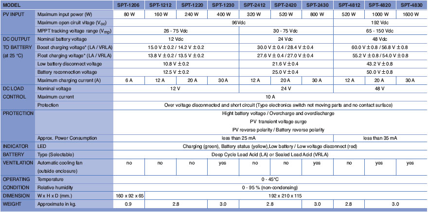
Table 2  Specifications of the SOLARCON SPT-series MPPT solar charge controller

How to choose MPPT solar charge controller for PV module and battery
Steps to consider for choosing MPPT solar charge controller
SPT-XXYY (XX is nominal battery voltage, YY is maximum charge current)
Find out what is nominal battery voltage that charge controller will charge and select XX
Find out what is Wp of PV module and
Select the suitable charge current (CC) = (Wp) / XX
Find out YY by multiply CC by safety factor (NEC requirement) = (CC) x 1.2
Select SOLARCON SPT-series model that covers YY
Check that Vpm(system) is in range that SPT-XXYY can handle (MPPT voltage range) 
If PV modules are in series, need to check that Vpm(system) = Vpm(module) x Module in series
If PV modules are in parallel, need to check that Vpm(system) = Vpm(module)
Check that Voc(system) is not more than SPT-XXYY range (Maximum open circuit voltage)
 
If PV modules are in series, need to check that Voc(system) = Voc(module) x Module in series
 
If PV modules are in parallel, need to check that Voc(system) = Voc(module)

Saturday, October 10, 2015

QUADCOPTER DESIGN

How To Build A Quadcopter – Choosing Hardware

If you are planning on building a quadcopter but not sure how, this is the right place for you. Doing research is pretty boring, so I am trying to put together a comprehensive tutorial about quadcopter, hope it helps you as much as it helped me.
Building a quadcopter from scratch takes a lot of time and effort. If you are inpatient, afraid of programming/maths and has a good budget, you can just buy a pre-built kit. You could get it assembled within minutes before it’s flying (For example, like this one). But I have to say, you are missing the fun part of building a quadcopter. From choosing the parts, designing the circuits, to programming, you will be involved in every aspect of building a quadcopter, and it’s FUN!
For more tutorials, check out this list. If you have any questions, just leave me with comments. Recently I am in love with mini quad, check out my mini quad FPV video playlist, it documents my FPV learning adventure. If you want to find out how to start in this hobby, check out myquadcopter beginner guide.
This blog post is divided into a three parts
  • What is a Quadcopter and How It Work
  • Quadcopter Components Introduction
  • Conclusion

What Is A QuadCopter and How It Works

QuadCopter is a helicopter with four rotors, so it’s also known as quadrotor. Because of its unique design comparing to traditional helicopters, it allows a more stable platform, making quadcopters ideal for tasks such as surveillance and aerial photography. And it is also getting very popular in UAV research in recent years.
The Quadcopters exist in many different sizes. From as small as a CD up to something as big as one meter in width.
On a regular helicopter has one big rotor to provide all the lifting power and a little tail rotor to offset the aerodynamic torque generated by the big rotor (without it, the helicopter would spin almost as fast as the propeller)
Unlike a helicopter, a quadrotor has four rotors all work together to produce upward thrust and each rotor lifts only 1/4 of the weight, so we can use less powerful and therefore cheaper motors. The quadcopter’s movement is controlled by varying the relative thrusts of each rotor.
These rotors are aligned in a square, two on opposite sides of the square rotate in clockwise direction and the other two rotate in the opposite direction. If all rotors turn in the same direction, the craft would spin would spin just like the regular helicopter without tail rotor. (if you are not sure what I mean, check out this video) Yaw is induced by unbalanced aerodynamic torques. The aerodynamic torque of the first rotors pair cancelled out with the torque created by the second pair which rotates in the opposite direction, so if all four rotors apply equal thrust the quadcopter will stay in the same direction.
quadcopter-station
To maintain balance the quadcopter must be continuously taking measurements from the sensors, and making adjustments to the speed of each rotor to keep the body level. Usually these adjustments are done autonomously by a sophisticated control system on the quadcopter in order to stay perfectly balanced. A quadcopter has four controllable degrees of freedom:Yaw, Roll, Pitch, and Altitude. Each degree of freedom can be controlled by adjusting the thrusts of each rotor.
Roll_Pitch_Yaw
  • Yaw (turning left and right) is controlled by turning up the speed of the regular rotating motors and taking away power from the counter rotating; by taking away the same amount that you put in on the regular rotors produces no extra lift (it won’t go higher) but since the counter torque is now less, the quadrotor rotates as explained earlier.3.- control becomes a matter of which motor gets more power and which one gets less.
  • Roll (tilting left and right) is controlled by increasing speed on one motor and lowering on the opposite one.
  • Pitch (moving up and down, similar to nodding) is controlled the same way as roll, but using the second set of motors. This may be kinda confusing, but roll and pitch are determined from where the “front” of the thing is, and in a quadrotor they are basically interchangeable; but do take note that you have to decide which way is front and be consistent or your control may go out of control.
quadcopter-rotating
quadcopter-foward
For example, to roll or pitch, one rotor’s thrust is decreased and the opposite rotor’s thrust is increased by the same amount. This causes the quadcopter to tilt. When the quadcopter tilts, the force vector is split into a horizontal component and a vertical component. This causes two things to happen: First, the quadcopter will begin to travel opposite the direction of the newly created horizontal component. Second, because the force vector has been split, the vertical component will be smaller, causing the quadcopter to begin to fall. In order to keep the quadcopter from falling, the thrust of each rotor must then be increased to compensate.
This illustrates how the adjustments made for each degree of freedom must work together to achieve a desired motion. Now, building and flying a quadrotor from a remote control is simple and fun and stuff, but people noting the inherently stable flight (in theory with equal speed of the motors the thing keeps itself level) and ease of control (only three functions and they are all basically take speed from one and put in the other), people love to make them autonomous (flies itself) and semi-autonomous (at least keeps itself level by responding to disturbances and error).

Quadcopter Components Introduction

There are sensors connected to a microcontroller to make the decision as to how to control the motors. Depending on how autonomous you want it to be, one or more of these sensors are used in combination.
In this section, I will talk about these essential quadcopter components:
  • Frame – The structure that holds all the components together. They need to be designed to be strong but also lightweight.
  • Rotors – Brushless DC motors that can provide the necessary thrust to propel the craft. Each rotor needs to be controlled separately by a speed controller.
  • Propeller
  • Battery – Power Source
  • IMU – Sensors
  • Microcontroller – The Brain
  • RC Transmitter
  • Optional
Before we go into explaining how to choose each components, we can take a look some quadcopters that people have built, and the parts they used to get a rough idea. I didn’t build these planes, so I can’t guarantee their performance.

Frame

Frame is the structure that holds all the components together. The Frame should be rigid, and be able to minimize the vibrations coming from the motors.
Aluminium-Frame
A QuadCopter frame consists of two to three parts which don’t necessarily have to be of the same material:
  • The center plate where the electronics are mounted
  • Four arms mounted to the center plate
  • Four motor brackets connecting the motors to the end of the arms
Most available materials for the frame are:
  • Carbon Fiber
  • Aluminium
  • Wood, such as Plywood or MDF (Medium-density fibreboard)
Carbon fiber is most rigid and vibration absorbent out of the three materials but also the most expensive.
Hollow aluminium square rails is the most popular for the QuadCopters’ arms due to its relatively light weight, rigidness and affordability. However aluminium could suffer from motor vibrations, as the damping effect is not as good as carbon fiber. In cases of severe vibration problem, it could mess up sensor readings.
Wood board such as MDF plates could be cut out for the arms as they are better at absorbing the vibrations than aluminium. Unfortunately the wood is not a very rigid material and can break easily in quadcopter crashes.
Although it is not as important as for the arms which of the three material to use for the center plate, plywood is most commonly seen because of its the light weight, easy to work with and good vibration absorbing features.
As for arm length, the term “motor-to-motor distance” is sometimes used, meaning the distance between the center of one motor to that of another motor of the same arm in the QuadCopter terminology.
QuadCopter-M2M-Distance
The motor to motor distance usually depends on the diameter of the propellers. To make you have enough space between the propellers and they don’t get caught by each other.

Brushless Motors

A little background of Brushless motor. They are a bit similar to normal DC motors in the way that coils and magnets are used to drive the shaft. Though the brushless motors do not have a brush on the shaft which takes care of switching the power direction in the coils, and this is why they are called brushless. Instead the brushless motors have three coils on the inner (center) of the motor, which is fixed to the mounting.
brushless_motor_1
On the outer side it contains a number of magnets mounted to a cylinder that is attached to the rotating shaft. So the coils are fixed which means wires can go directly to them and therefor there is no need for a brush.
brushless_motor
BrushlessMotor
Generally brushless motors spin in much higher speed and use less power at the same speed than DC motors. Also brushless motors don’t lose power in the brush-transition like the DC motors do, so it’s more energy efficient.
Brushless motors come in many different varieties, where the size and the current consumption differ. When selecting your brushless motor you should take care of the weight, the size, which kind of propeller you are going to use, so everything matches up with the current consumption. When looking for the brushless motors you should notice the specifications, especially the “Kv-rating“.
The Kv-rating indicates how many RPMs (Revolutions per minute) the motor will do if provided with x-number of volts. The RPMs can be calculated in this way: RPM=Kv*U An easy way to calculate rating of motor you need.
Make sure you buy the counter-rotating to counteract the torque effect of the props.

Propellers

On each of the brushless motors there are mounted a propeller.
You might not have noticed this on the pictures, but the 4 propellers are actually not identical. You will see that the front and the back propellers are tilted to the right, while the left and right propellers are tilted to the left.
Like I mentioned before, 2 rotors rotates in the opposite directions to the other two to avoid body spinning. By making the propeller pairs spin in each direction, but also having opposite tilting, all of them will provide lifting thrust without spinning in the same direction. This makes it possible for the QuadCopter to stabilize the yaw rotation, which is the rotation around itself.
images
The propellers come in different diameters and pitches (tilting). You would have to decide which one to use according to your frame size, and when that decision is made you should chose your motors according to that. Some of the standard propeller sizes used for QuadCopters are:
  • EPP1045 10 diameter and 4.5 pitch  this is the most popular one, good for mid-sized quads
  • APC 1047 10 diameter and 4.7 pitch  much similar to the one above
  • EPP0845  8 diameter and 4.5 pitch  regularly used in smaller quads
  • EPP1245  12 diameter and 4.5 pitch  used for larger quads which requires lot of thrust
  • EPP0938  9 diameter and 3.8 pitch  used in smaller quads
Aerodynamics is just way too complex for non-academic hobbyists. It’s even unlikely we can explain all that theory stuff in a few words. But in general when selecting propellers you can always follow these rules:
  1. The larger diameter and pitch the more thrust the propeller can generate. It also requires more power to drive it, but it will be able to lift more weight.
  2. When using high RPM (Revolutions per minute) motors you should go for the smaller or mid-sized propellers. When using low RPM motors you should go for the larger propellers as you can run into troubles with the small ones not being able to lift the quad at low speed.
To learn about what effects the type of material have, on flight performance, check out this post.

Analysis of Propeller Pitch, Diameter, and RPM

Pitch VS Diameter: the diameter basically means area while pitch means effective area. So with the same diameter, larger pitch propeller would generate more thrust and lift more weight but also use more power.
A higher RPM of the propeller will give you more speed and maneuverability, but it is limited in the amount of weight it will be able to lift for any given power. Also, the power drawn (and rotating power required) by the motor increases as the effective area of the propeller increases, so a bigger diameter or higher pitch one will draw more power at the same RPM, but will also produce much more thrust, and it will be able to lift more weight.
In choosing a balanced motor and propeller combination, you have to figure out what you want your quadcopter to do. If you want to fly around stably with heavy subject like a camera, you would probably use a motor that manages less revolutions but can provide more torque and a longer or higher pitched propeller (which uses more torque to move more air in order to create lift).

ESC – Electronic Speed Controller

The brushless motors are multi-phased, normally 3 phases, so direct supply of DC power will not turn the motors on. Thats where the Electronic Speed Controllers (ESC) comes into play. The ESC generating three high frequency signals with different but controllable phases continually to keep the motor turning. The ESC is also able to source a lot of current as the motors can draw a lot of power.
ESC-Turnigy-Plush
The ESC is an inexpensive motor controller board that has a battery input and a three phase output for the motor. Each ESC is controlled independently by a PPM signal (similar to PWM). The frequency of the signals also vary a lot, but for a Quadcopter it is recommended the controller should support high enough frequency signal, so the motor speeds can be adjusted quick enough for optimal stability (i.e. at least 200 Hz or even better 300 Hz PPM signal). ESC can also be controlled through I2C but these controllers are much more expensive.
When selecting a suitable ESC, the most important factor is the source current. You should always choose an ESC with at least 10 A or more in sourcing current as what your motor will require. Second most important factor is the programming facilities, which means in some ESC you are allowed to use different signals frequency range other than only between 1 ms to 2 ms range, but you could change it to whatever you need. This is especially useful for custom controller board.

Battery

As for the power source of the quadcopter, I would recommend LiPo Battery because firstly it is light, and secondly its current ratings meet our requirement. NiMH is also possible. They are cheaper, but it’s also a lot heavier than LiPo Battery.
Battery-Zippy-4000

Battery Voltage

LiPo battery can be found in a single cell (3.7V) to in a pack of over 10 cells connected in series (37V). A popular choice of battery for a QuadCopter is the 3SP1 batteries which means three cells connected in series as one parallel, which should give us 11.1V.

Battery Capacity

As for the battery capacity, you need to do some calculations on:
  • How much power your motors will draw?
  • Decide how long flight time you want?
  • How much influence the battery weight should have on the total weight?
A good rule of thumb is that you with four EPP1045 propellers and four Kv=1000 rated motor will get the number of minutes of full throttle flight time as the same number of amp-hours in your battery capacity. This means that if you have a 4000mAh battery, you will get around 4 minutes of full throttle flight time though with a 1KG total weight you will get around 16 minutes of hover.

Battery Discharge Rate

Another important factor is the discharge rate which is specified by the C-value. The C-value together with the battery capacity indicates how much current can be drawn from the battery.
Maximum current that can be sourced can be calculated as:
MaxCurrent = DischargeRate x Capacity
For example if there is a battery that has a discharge rate of 30C and a capacity of 2000 mAh. With this battery you will be able to source a maximum of 30Cx2000mAh = 60A. So in this case you should make sure that the total amount of current drawn by your motors won’t exceed 60A.
This tutorial about battery I found very informative. I did a math model to estimate the flight time, which might be helpful to you.

IMU – Inertial Measurement Unit

The Inertial Measurement Unit (IMU) is an electronic sensor device that measures the velocity, orientation and gravitational forces of the quadcopter. These measurements allow the controlling electronics to calculate the changes in the motor speeds.
The IMU is a combination of the 3-axis accelerometer and 3-axis gyroscope, together they represent a 6DOF IMU. Sometimes there is also an additional 3-axis magnetometer for better Yaw stability (in total 9DOF).

How does IMU work

The accelerometer measures acceleration and also force, so the downwards gravity will also be sensed. As the accelerometer has three axis sensors, we can work out the orientation of the device.
Accelerometer-3-axis
A gyroscope measure angular velocity, in other words the rotational speed around the three axis.
Gyroscope-3-axis

Using Only Accelerometer?

With the accelerometer alone, we should be able to measure the orientation with reference to the surface of earth. But the accelerometer tends to be very sensitive and unstable sometimes, when motor vibration is bad, it could mess up the orientation. Therefore we use a gyroscope to address this problem. With both the accelerometer and gyroscope readings we are now able to distinguish between movement and vibration.

Using Only Gyroscope?

Since the gyroscope can tell us the rotational movement, why can’t we just use the gyroscope alone?
The gyroscope tends to drift a lot, which means that if you start rotating the sensor, the gyroscope will output the angular velocity, but when you stop it doesn’t necessarily go back to 0 deg/s. If you then just used the gyroscope readings you will get an orientation that continues to move slowly (drifts) even when you stopped rotating the sensor. This is why both sensors has to be used together to calculate a good and useful orientation.

Magnetometer

The accelerometer cannot sense yaw rotation like it can with roll and pitch, and therefore a magnetometer is sometimes used.
A magnetometer measures the directions and strength of the magnetic field. This magnetic sensor can be used to determine which way is south and north. The pole locations are then used as a reference together with the Yaw angular velocity around from the gyroscope, to calculate a stable Yaw angle.
I am trying to keep the theory and maths minimal here, and I will go into more detail in the next couple of tutorials.

Buying an IMU

These three sensors are available individually on the market. But it is easier for development to get an IMU sensor board with the first two sensors (6DOF) or all three sensors (9DOF).
9DOF-Stick-Front
The raw sensor boards can communicate with the microcontroller via I2C or analogue. Digital boards that support I2C is easier and faster for development, but Analogue ones are cheaper.
There are even complete IMU units with processor available. Usually the processor is a small 8-bit microprocessor which runs computations some kind of algorithms to work out the Pitch, Roll and Yaw. The calculated data will then be put out on a serial bus or sometimes also available by I2C or SPI.
The choice of IMU is going to narrow down what type of controller board you can use. So before purchasing an IMU boards you should find out information about the controller boards. Some controller boards even comes with built-in sensors.
Some commercially available IMU sensors boards:
IMU with processor:

Flight Controller – Controlling electronics

You can either buy a controller board that is specially designed for quadcopter or buy all the parts and assemble one yourself. Some of the controller boards already contain the required sensors while other requires you to buy these on a separate board.
Here is a comprehensive list of ready to go flight controller boards:
The AeroQuad MEGA Shield The AeroQuad board is a shield for the Arduino, either the Arduino UNO or the Arduino MEGA. The AeroQuad board requires the Sparkfun 9DOF stick which is soldered to the shield.
The ArduPilot board contains an ATMEGA328, the same as on the Arduino UNO. Like the AeroQuad shield this board doesn’t contain any sensors either. You would have to buy the ArduIMU and connect it to the board to use it.
The OpenPilot is a more advanced board which contains a 72MHz ARM Cortex-M3 processor, the STM32. The board also includes a 3-axis accelerometer and 3-axis gyroscope. Together with the board comes a great piece of software for the PC to calibrate, tune and especially set waypoints for your QuadCopter if you have installed a GPS module which I will be talking more about in the next section.

Make You Own Quadcopter Controller Board

Alternatively you can also use general purpose microcontroller, such as Arduino, to build your own flight controller.

RC Transmitter

QuadCopters can be programmed and controlled in many different ways but the most common ones are by RC transmitter in either Rate (acrobatic) or Stable mode. The difference is the way the controller board interprets the orientations feedback together with your RC transmitter joysticks.
In Rate mode only the Gyroscope values are used to control the quadcopter. The joysticks on your RC transmitter are then used to control and set the desired rotation speed of the 3 axes, though if you release the joysticks it does not automatically re-balance. This is useful when doing acrobatics with your quadcopter as you can tilt it a bit to the right, release your joysticks, and then your quadcopter will keep that set position.
For the beginners the Rate mode might be too difficult, and you should start with the Stable mode. All the sensors are used to determine the quadcopters orientation in the stable mode. The speed of the 4 motors will be adjusted automatically and constantly to keep the quadcopter balanced. You control and change the angle of the quadcopter with any axis using the joystick. For example to go forward, you can simply tilt one of the joysticks to change the pitch angle of the quadcopter. When releasing the joystick, the angle will be reset and the quadcopter will be balanced again.

Optional Components

After buying all the necessary parts, and you are still not broke, you might consider other popular optional components such as GPS modules, ultrasonic sensors, barometers etc. They can enhance the performance of your quadcopter, and bring more features.
A GPS module talks to the satellite and retrieve accurate location information. We can use this information to calculate speed and path. It is especially useful for autonomous quadcopters which needs to know its exact position and which way to fly.
An ultrasonic sensor measures the distance to the ground, i.e. altitude. This is useful if you want to keep your quadcopter a certain distance from the ground without having to adjust the height it’s flying at constantly yourself. Most of these sensors has a range between 20cm to 7m.
When you gets higher, you might want to use a barometer. This sensor measures humidity and pressure to work out the altitude, so when the quadcopter is close to the ground (where these two factors doesn’t change much), it becomes ineffective. Therefore it is also common to use both of them at the same time.

Conclusion

Hopefully this article has given you a better understanding what each part of the quadcopter does, and how to go about selecting the right product for your quadcopter. To learn more about flying a Quadcopter, see this beginner guide about control.
Please do not hesitate writing a comment or giving us some feedback on this article. The next post will be about the software side of the quadcopter.

What is the difference between Socket and Port?

Socket Sockets allow communication between two different processes on the same or different machines. To be more precise, it's a way to ...