PID controller theory
- This section describes the parallel or non-interacting form of the PID controller. For other forms please see the section Alternative nomenclature and PID forms.
The PID control scheme is named after its three correcting terms, whose sum constitutes the manipulated variable (MV). The proportional, integral, and derivative terms are summed to calculate the output of the PID controller. Defining  as the controller output, the final form of the PID algorithm is:
 as the controller output, the final form of the PID algorithm is:
where
 : Proportional gain, a tuning parameter
 : Integral gain, a tuning parameter
 : Derivative gain, a tuning parameter
 : Error
 : Set Point
 : Process Variable
 : Time or instantaneous time (the present)
 : Variable of integration; takes on values from time 0 to the present
  .
.
Equivalently, the transfer function in the Laplace Domain of the PID controller is
where
 : complex number frequency
Proportional term
The proportional term produces an output value that is proportional to the current error value. The proportional response can be adjusted by multiplying the error by a constant Kp, called the proportional gain constant.
The proportional term is given by:
A high proportional gain results in a large change in the output for a given change in the error. If the proportional gain is too high, the system can become unstable (see the section on loop tuning). In contrast, a small gain results in a small output response to a large input error, and a less responsive or less sensitive controller. If the proportional gain is too low, the control action may be too small when responding to system disturbances. Tuning theory and industrial practice indicate that the proportional term should contribute the bulk of the output change.[citation needed]
In a real system, proportional-only control will leave an offset error in the final steady-state condition. Integral action is required to eliminate this error.
Integral term
The contribution from the integral term is proportional to both the magnitude of the error and the duration of the error. The integral in a PID controller is the sum of the instantaneous error over time and gives the accumulated offset that should have been corrected previously. The accumulated error is then multiplied by the integral gain ( ) and added to the controller output.
 ) and added to the controller output.
The integral term is given by:
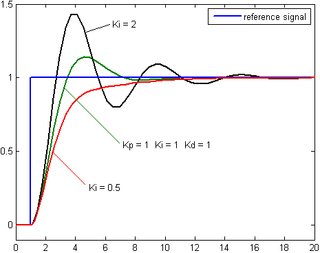
The integral term accelerates the movement of the process towards setpoint and eliminates the residual steady-state error that occurs with a pure proportional controller. However, since the integral term responds to accumulated errors from the past, it can cause the present value to overshoot the setpoint value (see the section on loop tuning).
Derivative term
The derivative of the process error is calculated by determining the slope of the error over time and multiplying this rate of change by the derivative gain Kd. The magnitude of the contribution of the derivative term to the overall control action is termed the derivative gain, Kd.
The derivative term is given by:
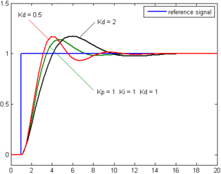
Derivative action predicts system behavior and thus improves settling time and stability of the system.[12][13] An ideal derivative is not causal, so that implementations of PID controllers include an additional low pass filtering for the derivative term, to limit the high frequency gain and noise.[14]Derivative action is seldom used in practice though - by one estimate in only 25% of deployed controllers[14] - because of its variable impact on system stability in real-world applications.[14]
Loop tuning
Tuning a control loop is the adjustment of its control parameters (proportional band/gain, integral gain/reset, derivative gain/rate) to the optimum values for the desired control response. Stability (no unbounded oscillation) is a basic requirement, but beyond that, different systems have different behavior, different applications have different requirements, and requirements may conflict with one another.
PID tuning is a difficult problem, even though there are only three parameters and in principle is simple to describe, because it must satisfy complex criteria within the limitations of PID control. There are accordingly various methods for loop tuning, and more sophisticated techniques are the subject of patents; this section describes some traditional manual methods for loop tuning.
Designing and tuning a PID controller appears to be conceptually intuitive, but can be hard in practice, if multiple (and often conflicting) objectives such as short transient and high stability are to be achieved. PID controllers often provide acceptable control using default tunings, but performance can generally be improved by careful tuning, and performance may be unacceptable with poor tuning. Usually, initial designs need to be adjusted repeatedly through computer simulations until the closed-loop system performs or compromises as desired.
Some processes have a degree of nonlinearity and so parameters that work well at full-load conditions don't work when the process is starting up from no-load; this can be corrected by gain scheduling (using different parameters in different operating regions).
Stability
If the PID controller parameters (the gains of the proportional, integral and derivative terms) are chosen incorrectly, the controlled process input can be unstable, i.e., its output diverges, with or without oscillation, and is limited only by saturation or mechanical breakage. Instability is caused by excess gain, particularly in the presence of significant lag.
Generally, stabilization of response is required and the process must not oscillate for any combination of process conditions and setpoints, though sometimesmarginal stability (bounded oscillation) is acceptable or desired.[citation needed]
Mathematically, the origins of instability can be seen in the Laplace domain.[15] The total loop transfer function is:
where
 : PID transfer function
 : Plant transfer function
The system is called unstable where the closed loop transfer function diverges for some  .[15] This happens for situations where
  . Typically, this happens when
  with a 180 degree phase shift. Stability is guaranteed when
  for frequencies that suffer high phase shifts. A more general formalism of this effect is known as the Nyquist stability criterion.
 .[15] This happens for situations where
  . Typically, this happens when
  with a 180 degree phase shift. Stability is guaranteed when
  for frequencies that suffer high phase shifts. A more general formalism of this effect is known as the Nyquist stability criterion.
Optimum behavior
The optimum behavior on a process change or setpoint change varies depending on the application.
Two basic requirements are regulation (disturbance rejection – staying at a given setpoint) and command tracking (implementing setpoint changes) – these refer to how well the controlled variable tracks the desired value. Specific criteria for command tracking include rise time and settling time. Some processes must not allow an overshoot of the process variable beyond the setpoint if, for example, this would be unsafe. Other processes must minimize the energy expended in reaching a new setpoint.
REF:wikipedia
REF:wikipedia


No comments:
Post a Comment